Deye SUN-6K-SG04LP3-EU User Manual
Hybrid inverter
Hide thumbs
Also See for SUN-6K-SG04LP3-EU:
- User manual (50 pages) ,
- User manual (51 pages) ,
- User manual (58 pages)

Subscribe to Our Youtube Channel
Related Manuals for Deye SUN-6K-SG04LP3-EU


Summary of Contents for Deye SUN-6K-SG04LP3-EU
- Page 1 Hybrid Inverter SUN-5K-SG04LP3-EU SUN-6K-SG04LP3-EU SUN-8K-SG04LP3-EU SUN-10K-SG04LP3-EU SUN-12K-SG04LP3-EU 05/28/2019 15:34:40 8.30 -3.00 -2.00 3.00 User Manual...
-
Page 2: Table Of Contents
Contents 1. Safety Introductions 01-02 ………………………………………………… 2. Product instructions 02-05 ………………………………………………… 2.1 Product Overview 2.2 Product Size 2.3 Product Features 2.4 Basic System Architecture 3. Installation 06-27 …………………………………………………………… 3.1 Parts list 3.2 Product handling requirements 3.3 Mounting instructions 3.4 Battery connection 3.5 Grid connection and backup load connection 3.6 PV Connection 3.7 CT Connection... -
Page 3: About This Manual
Documents must be stored carefully and be available at all �mes. Contents may be periodically updated or revised due to product development. The informa�on in this manual is subject to change without no�ce. The latest manual can be acquired via service@deye.com.cn 1. Safety Introduc�ons Labels descrip�on... - Page 4 · This chapter contains important safety and opera�ng instruc�ons. Read and keep this manual for future reference. · Before using the inverter, please read the instruc�ons and warning signs of the ba�ery and corresponding sec�ons in the instruc�on manual. · Do not disassemble the inverter. If you need maintenance or repair, take it to a professional service center.
-
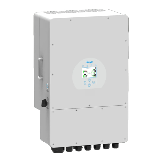
Page 5: Product Overview
2.1 Product Overview 1: Inverter indicators 7: Meter-485 port 13: *Circuit breaker of Grid 2: LCD display 8: Ba�ery input connectors 14: Load 3: Func�on bu�ons 9: Func�on port 15: Generator input 4: Power on/off bu�on 10: Modbus port 16: WiFi Interface 5: DC switch 11: BMS port 17: DRM port... -
Page 6: Product Size
2.2 Product Size 422.0 mm 450.9 mm Inverter Size 279.0 mm 422.0 mm 254.0 mm 240.00 mm - 04 -... -
Page 7: Product Features
2.3 Product Features - 230V/400V Three phase Pure sine wave inverter. - Self-consump�on and feed-in to the grid. - Auto restart while AC is recovering. - Programmable supply priority for ba�ery or grid. - Programmable mul�ple opera�on modes: On grid, off grid and UPS. - Configurable ba�ery charging current/voltage based on applica�ons by LCD se�ng. -
Page 8: Parts List
3. Installa�on 3.1 Parts List Check the equipment before installa�on. Please make sure nothing is damaged in the package. You should have received the items in the following package: Stainless steel an�-collision Hybrid inverter Wall moun�ng bracket x1 bolt M8×80 User manual Parallel communica�on... -
Page 9: Product Handling Requirements
3.2 Product handling requirements Li� the inverter out of the packing box and transport it to designated installa�on loca�on. transport CAUTION: Improper handling may cause personal injury! • Arrange an appropriate number of personnel to carry the inverter according to its weight, and installa�on personnel should wear protec�ve equipment such as an�-impact shoes and gloves. - Page 10 Please AVOID direct sunlight, rain exposure, snow laying up during installa�on and opera�on. Before connec�ng all wires, please take off the metal cover by removing screws as shown below: Installa�ons Tools Installa�on tools can refer to the following recommended ones. Also, use other auxiliary tools on site.
- Page 11 Considering the following points before selec�ng where to install: · Please select a ver�cal wall with load-bearing capacity for installa�on, suitable for installa�on on concrete or other non-flammable surfaces,installa�on is shown below. · Install this inverter at eye level in order to allow the LCD display to be read at all �mes. ·...
- Page 12 Inverter hanging plate installa�on 3.4 Ba�ery connec�on For safe opera�on and compliance, a separate DC over-current protector or disconnect device is required between the ba�ery and the inverter. In some applica�ons, switching devices may not be required but over-current protectors are s�ll required. Refer to the typical amperage in the table below for the required fuse or circuit breaker size.
- Page 13 All wiring must be performed by a professional person. Connec�ng the ba�ery with a suitable cable is important for safe and efficient opera�on of the system. To reduce the risk of injury, refer to Chart 3-2 for recommended cables. Please follow below steps to implement ba�ery connec�on: 1.
- Page 14 3.4.2 Func�on port defini�on Inverter CN1: TEMP: 1,2 CN2: G_start: 1,2 CT_1: 3,4 G_valve: 3,4 Parallel_A Parallel_B Meter-485 CT_2: 5,6 Grid_Ry: 5,6 CT_3: 7,8 RSD: 7+, 8- Modbus 1 2 3 4 5 6 7 8 1 2 3 4 5 6 7 8 Parallel A: Parallel communica�on port 1 (CAN interface).
- Page 15 3.4.3 Temperature sensor connec�on for lead-acid ba�ery Inverter Temp. CT - 13 -...
- Page 16 3.5 Grid connec�on and backup load connec�on · Before connec�ng to the grid, a separate AC breaker must be installed between the inverter and the grid, and also between the backup load and the inverter. This will ensure the inverter can be securely disconnected during maintenance and fully protected from over current.
- Page 17 GRID LOAD GEN PORT LOAD T (L3) S (L2) R (L1) T (L3) GRID S (L2) R (L1) T (L3) S (L2) R (L1) GEN PORT LOAD T (L3) T (L3) S (L2) S (L2) R (L1) R (L1) Thread the 4 wires of Load terminals Thread the 4 wires of GEN terminals through the magne�c ring.
-
Page 18: Pv Connection
Be sure that AC power source is disconnected before a�emp�ng to wire it to the unit. 3. Then, insert AC output wires according to polari�es indicated on the terminal block and �ghten terminal. Be sure to connect corresponding N wires and PE wires to related terminals as well. 4. - Page 19 3.6.1 PV Module Selec�on: When selec�ng proper PV modules, please be sure to consider below parameters: 1) Open circuit Voltage (Voc) of PV modules not exceeds max. PV array open circuit voltage of inverter. 2) Open circuit Voltage (Voc) of PV modules should be higher than min. start voltage. 3) The PV modules used to connected to this inverter shall be Class A ra�ng cer�fied according to lEC 61730.
-
Page 20: Cable Type
Safety Hint: Please use approved DC cable for PV system. Cross section(mm ) Cable type Range Recommended value Industry generic PV cable 2.5-4.0 2.5(12AWG) (model: PV1-F) (12-10AWG) Chart 3-6 The steps to assemble the DC connectors are listed as follows: a)Strip off... - Page 21 Please use its own DC power connector from the inverter accessories. Do not interconnect the connectors of different manufacturers.Max. DC input current should be 20A. if exceeds, it may damage the inverter and it is not covered by Deye warranty. - 19 -...
-
Page 22: Ct Connection
3.7 CT Connec�on GRID Ground Inverter Black wire White wire 6 7 8 Arrow pointing inverter Grid *Note:when the reading of the load power on the LCD is not correct, please reverse the CT arrow. - 20 -... -
Page 23: Meter Connection
3.7.1 Meter Connec�on GRID Ground Inverter Parallel_A Parallel_B Meter-485 port Three-Phase Smart Meter RS485A Grid RS485B Three-Phase Smart Meter (1,4,7,10) (3,6,9,10) RS 485 CHINT meter CHNT DTSU666 GRID Ground Inverter Parallel_A Parallel_B Meter-485 port RS485B RS485A 1 2 3 4 5 6 7 8 Eastron Grid... -
Page 24: Earth Connection(Mandatory)
Note: When the inverter is in the off-grid state, the N line needs to be connected to the earth. 3.8 Earth Connec�on(mandatory) Ground cable shall be connected to ground plate on grid side, this prevents electric shock if the original protec�ve conductor fails. Earth connec�on (Copper wires) Model Wire Size... -
Page 25: Wiring System For Inverter
3.10 Wiring System for Inverter - 23 -... -
Page 26: Wiring Diagram
3.11 Wiring diagram - 24 -... -
Page 27: Backup Load
L wire N wire PE wire Ground Inverter ①DC Breaker Battery pack ②AC Breaker ③AC Breaker CT1 CT2 Grid ④AC Breaker Home Load ① DC Breaker for battery SUN 5K-SG-EU: 150A DC breaker Backup Load SUN 6K-SG-EU: 200A DC breaker SUN 8K-SG-EU: 250A DC breaker SUN 10K-SG-EU: 300A DC breaker SUN 12K-SG-EU: 300A DC breaker... -
Page 28: Typical Application Diagram Of Diesel Generator
3.12 Typical applica�on diagram of diesel generator L wire N wire PE wire coil relay open contact Backup Load ②AC GS (diesel generator startup signal) Breaker G-start (1,2): dry contact signal for startup the diesel generator. CN2: Ground Inverter ①DC Breaker ③AC Breaker Battery pack... - Page 29 3.13 Three phase parallel connec�on diagram Max. 10pcs parallel for on-grid and off-grid opera�on. L wire N wire PE wire Inverter No.3 (slave) Parallel_A Parallel_B Meter-485 Ground Inverter ① Inverter ④ ⑤ No.2 (slave) Ground ⑦ ② ⑥ Inverter No.1 (master) Ground ③...
-
Page 30: Operation
4. OPERATION 4.1 Power ON/OFF Once the unit has been properly installed and the ba�eries are connected well, simply press On/Off bu�on(located on the le� side of the case) to turn on the unit. When system without ba�ery connected, but connect with either PV or grid, and ON/OFF bu�on is switched off, LCD will s�ll light up(Display will show OFF), In this condi�on, when switch on ON/OFF bu�on and select NO ba�ery,system can s�ll working. -
Page 31: Lcd Display Icons
5. LCD Display Icons 5.1 Main Screen The LCD is touchscreen, below screen shows the overall informa�on of the inverter. 05/28/2019 15:34:40 8.30 -3.00 -2.00 3.00 1.The icon in the center of the home screen indicates that the system is Normal opera�on. If it turns into "comm./F01~F64"... -
Page 32: Advanced Function
5.1.1 LCD opera�on flow chart Solar Page Solar Graph Grid Page Grid Graph Inverter Page Main Screen Battery Page BMS Page Load Page Load Graph Battery Setting System Work Mode Grid Setting System Setup Gen Port Use Basic Setting Advanced Function Device info - 30 -... -
Page 33: Solar Power Curve
5.2 Solar Power Curve Solar This is Solar Panel detail page. ③ ① ① Solar Panel Genera�on. Power: 1560W Today=8.0 KWH Voltage, Current, Power for each MPPT. ② ② PV1-V: 286V PV2-V: 45V Total =12.00 KWH ③ Solar Panel energy for Day and Total. PV1-I: 5.5A PV2-I: 0.0A PV1-P: 1559W PV2-P: 1W... -
Page 34: Curve Page-Solar & Load & Grid
Li-BMS Mean Voltage:50.34V Charging Voltage :53.2V Batt Total Current:55.00A Discharging Voltage :47.0V Data Mean Temp :23.5C Charging current :50A Total SOC :38% Discharging current :25A Discharge Dump Energy:57Ah Details Data Request Force Charge U:49.58V Request Force Charge: It indicates the I:2.04A BMS requests hybrid inverter to charge Power: 101W... -
Page 35: System Setup Menu
5.4 System Setup Menu System Setup This is System Setup page. System Work Mode Battery Setting Gen Port Grid Setting Basic Advanced Device Info. Setting Function 5.5 Basic Setup Menu Basic Setting Factory Reset: Reset all parameters of the inverter. Lock out all changes: Enable this menu for se�ng Time Syncs Beep... -
Page 36: Battery Setup Menu
5.6 Ba�ery Setup Menu Ba�ery capacity: it tells Deye hybrid inverter to know Battery Setting your ba�ery bank size. Batt Mode Use Ba� V: Use Ba�ery Voltage for all the se�ngs (V). Lithium 400Ah Batt Capacity Batt Use Ba� %: Use Ba�ery SOC for all the se�ngs (%). - Page 37 Generator This page tells generator output voltage, frequency, power. And, how much energy is used from generator. Power: 6000W Today=10 KWH Total =10 KWH P_L1: 2KW V_L1: 230V P_L2: 2KW V_L2: 230V P_L3: 2KW V_L3: 230V Battery Setting Lithium Mode: This is BMS protocol.Please reference the document(Approved Ba�ery).
-
Page 38: System Work Mode Setup Menu
5.7 System Work Mode Setup Menu System Work Mode Work Mode Selling First: This Mode allows hybrid inverter to sell 12000 back any excess power produced by the solar panels to Selling First Max Solar Power the grid. If �me of use is ac�ve, the ba�ery energy also Work Zero Export To Load Solar Sell... - Page 39 Time of use: it is used to program when to use grid or generator to charge the ba�ery, and when to discharge the ba�ery to power the load. Only �ck "Time Of Use" Time Of Use then the follow items (Grid, charge, �me, power etc.) Time Power Batt...
-
Page 40: Grid Setup Menu
5.8 Grid Setup Menu Grid Setting/Grid code selection Grid Mode:General Standard、UL1741 & IEEE1547、 CPUC RULE21、SRD-UL-1741、CEI 0-21、Australia A、 Grid Mode General Standard 0/11 Australia B、Australia C、EN50549_CZ-PPDS(>16A)、 Phase Type Grid Frequency 50HZ Grid NewZealand、VDE4105、OVE-Direc�ve R25. Set1 0/120/240 60HZ Please follow the local grid code and then choose the 0/240/120 corresponding grid standard. - Page 41 Grid Setting/F(W) FW: this series inverter is able to adjust inverter output power according to grid frequency. F(W) Droop F: percentage of nominal power per Hz Over frequency Droop F %PE/Hz For example, “Start freq F>50.2Hz, Stop freq F<51.5, Grid Set4 Stop freq F Start freq F...
-
Page 42: Generator Port Use Setup Menu
5.9 Generator Port Use Setup Menu GEN PORT USE Generator input rated power: allowed Max. power from diesel generator. Mode GEN connect to grid input: connect the diesel generator to the Generator Input GEN connect to Grid input grid input port. PORT Rated Power Smart Load Output: This mode u�lizes the Gen input connec�on... -
Page 43: Device Info Setup Menu
Advanced Function This is for Wind Turbine DC 1 for WindTurbine DC 2 for WindTurbine 16.5 Wind 0.0A 210V 9.0A Set2 110V 1.5A 230V 10.5A 130V 3.0A 250V 12.0A 150V 4.5A 270V 13.5A 170V 6.0A 290V 15.0A 190V 7.5A 310V 16.5A Advanced Function Ex_Meter For CT: when using zero-export to CT mode,... -
Page 44: Limitation Of Liability
Mode II: With Generator AC cable DC cable Solar Backup Load On-Grid Home Load Grid Battery Generator Mode III: With Smart-Load AC cable DC cable Solar Backup Load On-Grid Home Load Grid Battery Smart Load Mode IV: AC Couple On-GEN+AC couple AC cable DC cable Solar... - Page 45 Error code Description Solutions 1,Check the PV input polarity DC input polarity reverse fault 2,Seek help from us, if can not go back to normal state. 1,The BUS voltage can t be built from PV or battery. DC_START_Failure 2,Restart the inverter, If the fault still exists, please contact us for help 1.
- Page 46 Error code Description Solutions BUS over current. 1, Check the PV input current and battery current setting Tz_HV_Overcurr_fault 2. Restart the system 2~3 times. 3. If the fault still exists, please contact us for help. Remotely shutdown Tz_EmergStop_Fault 1, it tells the inverter is remotely controlled. Leakage current fault 1.
- Page 47 Error code Description Solutions 1,Please check each battery status, such as voltage/ SOC and parameters etc., and make sure all the parameters are same. backup battery fault 2,If the fault still exists, please contact us for help Grid frequency out of range 1.
- Page 48 Under the guidance of our company, customers return our products so that our company can provide service of maintenance or replacement of products of the same value. Customers need to pay the necessary freight and other related costs. Any replacement or repair of the product will cover the remaining warranty period of the product.
-
Page 49: Datasheet
8. Datasheet SUN-5K- SUN-6K- SUN-8K- SUN-10K- SUN-12K- Model SG04LP3-EU SG04LP3-EU SG04LP3-EU SG04LP3-EU SG04LP3-EU Battery Input Data Ba�ery Type Lead-acid or Lithium-ion Ba�ery Voltage Range(V) 40-60 Max. Charging Current(A) Max. Discharging Current(A) Charging Strategy for Li-ion Ba�ery Self-adap�on to BMS Number of Ba�ery Input PV String Input Data Max. - Page 50 DC Component Monitoring Ground Fault Current Monitoring Power Network Monitoring Island Protec�on Monitoring Earth Fault Detec�on DC Input Switch Overvoltage Load Drop Protec�on Residual Current (RCD) Detec�on Surge Protec�on Level TYPE II(DC), TYPE II(AC) Interface Display LCD+LED Communica�on Interface RS232, RS485, CAN Monitor Mode GPRS/WIFI/Bluetooth/4G/LAN(op�onal) General Data...
- Page 51 9. Appendix I Defini�on of RJ45 Port Pin for BMS BMS Port RS485 Pin 485_B 1 2 3 4 5 6 7 8 485_A CAN-H CAN-L GND_485 485_A 485_B Defini�on of RJ45 Port Pin for Meter-485 Meter-485 Port Meter-485 Pin METER-485-B METER-485-A 1 2 3 4 5 6 7 8...
- Page 52 RS232 WIFI/RS232 D-GND 12Vdc WIFI/RS232 This RS232 port is used to connect the wifi datalogger - 50 -...
- Page 53 DRM:It is used to accept the external control command. Defini�on of RJ45 Port Pin for DRM 1 2 3 4 5 6 7 8 DI 1 DI 2 DI 3 DI 4 Reserved Reserved (PIN 6 REF_2) PIN 5 REF_1 100% PIN 4 DI 4 PIN 3 DI 3...
-
Page 54: Appendix
· Low Voltage Directive ����/��/EU (LVD) · Restriction of the use of certain hazardous substances ����/��/EU (RoHS) NINGBO DEYE INVERTER TECHNOLOGY CO., LTD. confirms herewith that the products described in this document are in compliance with the fundamental requirements and other relevant provisions of the above mentioned directives. -
Page 55: Eu Declaration Of Conformity
Models: SUN-5K-SG04LP3-EU;SUN-6K-SG04LP3-EU;SUN-8K-SG04LP3-EU;SUN-10K-SG04LP3-EU; SUN-12K-SG04LP3-EU; Name and address of the manufacturer: Ningbo Deye Inverter Technology Co., Ltd. No. 26 South YongJiang Road, Daqi, Beilun, NingBo, China This declaration of conformity is issued under the sole responsibility of the manufacturer. Also this product is under manufacturer’s warranty. - Page 56 Add.: No.26 South YongJiang Road, Daqi, Beilun, NingBo, China. Tel.: +86 (0) 574 8622 8957 Fax.: +86 (0) 574 8622 8852 E-mail: service@deye.com.cn Web.: www.deyeinverter.com...
Need help?
Do you have a question about the SUN-6K-SG04LP3-EU and is the answer not in the manual?
Questions and answers