Table of Contents
Advertisement
Quick Links
Installation Manual
MULTI FUNCTION DISPLAY
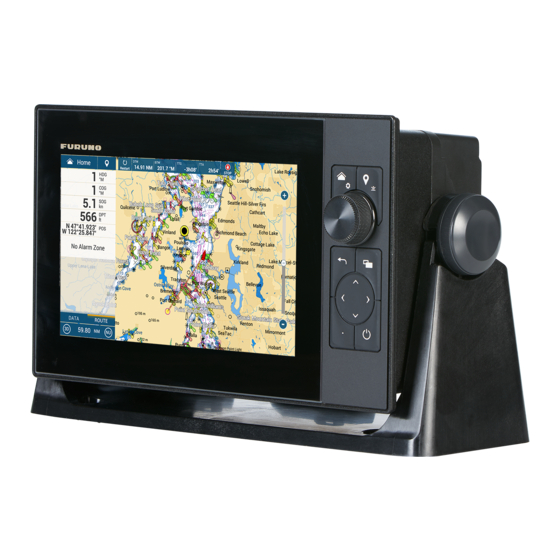
TZT9F
Model
SAFETY INSTRUCTIONS ................................................................................................ i
SYSTEM CONFIGURATION ........................................................................................... ii
EQUIPMENT LISTS........................................................................................................ iv
1. MOUNTING..............................................................................................................1-1
1.1 Installation of Multi Function Display..................................................................................1-1
1.2 Installation of Transducers.................................................................................................1-7
2. WIRING....................................................................................................................2-1
2.1 Interface Connections (Rear of Unit) .................................................................................2-1
2.2 Composite Connector ........................................................................................................2-2
2.3 How to Secure and Waterproof Connections.....................................................................2-2
2.4 Power Cable ......................................................................................................................2-3
2.5 MULTI Cable......................................................................................................................2-3
2.6 DRS Radar Sensor Connections .......................................................................................2-4
2.7 Network Connection with Other TZT Series Units .............................................................2-4
2.8 NMEA 2000 Connector ......................................................................................................2-4
2.9 Transducer (Option)...........................................................................................................2-9
2.10 Example TZT9F System Configurations ..........................................................................2-10
3. HOW TO SET UP THE EQUIPMENT......................................................................3-1
3.1 How to Set Time Zone, Time Format and Language.........................................................3-4
3.2 How to Set Units of Measurement .....................................................................................3-6
3.3 Initial Setup ........................................................................................................................3-7
3.4 How to Set Up the Radar .................................................................................................3-13
3.5 How to Set Up the Fish Finder.........................................................................................3-16
3.6 Wireless LAN Setting .......................................................................................................3-21
3.7 Ferry Mode.......................................................................................................................3-23
3.8 How to Manage Your Charts............................................................................................3-23
3.9 IP Camera Setup .............................................................................................................3-26
APPX. 1 TRANSDUCER LIST .................................................................................AP-1
PACKING LIST(S) ....................................................................................................... A-1
OUTLINE DRAWING(S) .............................................................................................. D-1
INTERCONNECTION DIAGRAM(S) ........................................................................... S-1
www.furuno.com
All brand and product names are trademarks, registered trademarks or service marks of their respective holders.
Advertisement
Table of Contents

Related Manuals for Furuno TZtouch2 TZTL12F


Summary of Contents for Furuno TZtouch2 TZTL12F
-
Page 1: Table Of Contents
3.8 How to Manage Your Charts....................3-23 3.9 IP Camera Setup ......................3-26 APPX. 1 TRANSDUCER LIST .................AP-1 PACKING LIST(S) ....................... A-1 OUTLINE DRAWING(S) ....................D-1 INTERCONNECTION DIAGRAM(S) ................S-1 www.furuno.com All brand and product names are trademarks, registered trademarks or service marks of their respective holders. - Page 2 ・FURUNO Authorized Distributor/Dealer 9-52 Ashihara-cho, Nishinomiya, 662-8580, JAPAN A : OCT 2020 Printed in Japan All rights reserved. F : JUN . 04, 2024 Pub. No. IME-45090-F (REFU ) TZT9F 0 0 0 1 9 7 9 0 7 1 5...
-
Page 3: Safety Instructions
SAFETY INSTRUCTIONS Indicates a potentially hazardous situation which, if not WARNING avoided, could result in death or serious injury. Indicates a potentially hazardous situation which, if not CAUTION avoided, may result in minor or moderate injury. (Examples of symbols) Warning, Caution Prohibitive Action Mandatory Action WARNING... -
Page 4: System Configuration
4 units) can be connected. NavNet TZtouch (TZT9/14/BB) cannot be connected. See page iii for TZT series compatible combinations. : FURUNO networks allow a maximum of three HUB-101 units on the same network. : DRS6A-NXT is rated for either 12 V or 24 V DC power supply. - Page 5 SYSTEM CONFIGURATION TZT series network connection The TZT series can be connected on the same network with the following combinations. TZtouch: TZtouch2: TZtouchXL: TZT9/14/BB TZTL12F/15F/TZT2BB TZT10X/13X/16X/22X/24X TZtouch3: TZT9F/12F/16F/19F...
-
Page 6: Equipment Lists
EQUIPMENT LISTS Standard supply Name Type Code No. Remarks Multi Function Display TZT9F CP19-02701 001-587-750 Installation Materials CP19-02702 001-587-760 Cable Assembly MJ-A3SPF0019-035C 000-156-058 Accessories FP26-00401 001-175-940 Flush Mounting Tem- C42-02003 001-197-909 plate Operator’s Guide OSE-45120-* 000-197-102-** Installation Manual IME-45090-* 000-197-907-** Spare Parts SP19-01601 001-587-730... - Page 7 EQUIPMENT LISTS Name Type Code No. Remarks External Buzzer OP03-136 000-086-443 Buzzer: PKB5-3A40 Rectifier PR-62 000-013-484 100 VAC 000-013-485 110 VAC 000-013-486 220 VAC 000-013-487 230 VAC AC/DC Power Supply PR-241 000-037-820 Unit Ferrite Core OP86-11 000-594-450 For PR-241 Cable Assy. FRU-F12F12-100C 001-560-390 FRU-F12F12-200C...
- Page 8 EQUIPMENT LISTS Name Type Code No. Remarks CHIRP Transducer TM150M 000-035-500 300 W (for internal fish finder) B-75L 000-035-501 B-75H 000-035-502 600 W B-175H 000-035-504 1 kW B-175L 000-035-503 CHIRP Transducer PM111LHG 000-027-404 2 kW (Requires DFF3-UHD) CM599LHG 000-027-406 2 to 3 kW CM599LM 000-027-407 Thru-Hull Pipe...
-
Page 9: Mounting
MOUNTING Installation of Multi Function Display The TZT9F is designed to be mounted in a console or panel, or mounted on a desktop. The installer of this equipment must read and follow the descriptions in this manual. Wrong installation or maintenance can void the warranty. Mounting considerations When selecting a mounting location for your TZT9F, keep the following in mind: •... - Page 10 1. MOUNTING 1.1.1 Desktop mounting Your TZT9F is shipped with a bracket for desktop mounting. The following procedure shows how to install the unit on a desktop. 1. Place the unit face-down on a soft/clean surface, then unfasten the knob bolts on either side of the unit.
- Page 11 1. MOUNTING 1.1.2 Flush mounting Referring to the figure below, select a flat mounting location. Read the installation in- structions before starting. Pay particular attention to the notes; failure to follow these instructions may cause damage to the unit. Note: Ensure the mounting location is flat, with no indents or protrusions, to allow a secure fit.
- Page 12 1. MOUNTING 5. Connect all cables at the back of the TZT9F. (See section 2.1) 6. Attach flush mount sponges to the bezel of TZT9F. Flush mount sponge 9H (2 pcs.) Flush mount sponge 9V (2 pcs.) Peel off the release paper. Unit (Rear Side) Attach mount sponge on the highlighted area.
- Page 13 1. MOUNTING 9. Fasten each wing bolt (4 pcs.) so that the protector for screw touches the mount- ing panel. 10. Fasten the wing nuts tightly. Wing bolt TZT unit TZT unit Wing nut Flush mounting fixture Protector for screw Mounting panel Note: Use of excessive torque when fastening the wing bolts can cause the flush mount fixture to tilt or warp.
- Page 14 1. MOUNTING 3. Set the F Mount Panel to the TZT9F unit, then using the hex bolts attached to TZT9F, fix the F Mount Panel to the unit. TZT unit TZT unit Hex bolt Hex bolt Frontmount panel 4. Connect necessary cable, referring to chapter 2. 5.
-
Page 15: Installation Of Transducers
1. MOUNTING Installation of Transducers CAUTION Do not cover the transducer with FRP resin. The heat generated when the resin hardens may damage the transducer. CHIRP transduc- ers are especially vulnerable to heat. There are three methods for installing the transducer on the ship (thru-hull mount, in- side the hull and transom mount) and one of those methods is to be selected accord- ing to the structure of the ship. - Page 16 1. MOUNTING 1.2.1 How to mount a transducer through the hull Transducer mounting location The thru-hull mount transducer provides the best performance of all, since the trans- ducer protrudes from the hull and the effect of air bubbles and turbulence near the hull skin is reduced.
- Page 17 1. MOUNTING Installation procedure 1. With the boat hauled out of the water, mark the location chosen for mounting the transducer on the bottom of the hull. 2. If the hull is not level within 15° in any direction, fairing blocks made out of teak should be used between the transducer and hull, both inside and outside, to keep the transducer face parallel with the water line.
- Page 18 1. MOUNTING 1.2.2 How to mount a transducer inside the hull NOTICE This installation method affects the ability to detect the bottom, fish and other objects because the ultrasound pulse is weakened when it passes through the hull. Therefore, refrain from this mounting method for a transducer that supports the RezBoost™...
- Page 19 (power switch) to turn the power on. 4. After the startup procedure completes (approx. 90 seconds), the last used display appears. Tap the Water [FURUNO] icon ( ) to show the home screen and display mode settings. See Hull plate section 3.3 for how to use the menu.
- Page 20 It takes 24 to 72 hours to harden completely. 5. Turn the power on and change the menu setting as shown below. See section 3.3 for how to use the menu. 1) Tap the [FURUNO] icon ( ) to show the home screen and dis- play mode settings.
- Page 21 1. MOUNTING 1.2.3 How to install the transom mount transducer The optional transom mount transducer is very commonly employed, usually on relatively small I/O or outboard boats. Do not use this method on an inboard motor boat because turbulence is created by the propeller ahead of the transducer. DO NOT over-tighten screws, to prevent damage to the transducer.
- Page 22 1. MOUNTING Transducer preparation Before putting your boat in water, wipe the face of the transducer thoroughly with a liquid detergent. This will lessen the time necessary for the transducer to have good contact with the water. Otherwise the time required for complete "saturation" will be lengthened and performance will be reduced.
- Page 23 1. MOUNTING Mount the sensor close to the centerline of your boat. On slower heavier displacement hulls, posi- tioning it farther from the centerline is acceptable. For single drive boat, mount on the star-board side at least 75 mm (3") beyond the swing radius of the propeller, as shown in the right figure.
- Page 24 1. MOUNTING Adjustments 1. Using a straight edge, sight the underside of the sensor relative to the underside of the hull. The stern of the sensor should be 1-3 mm (1/16-1/8”) below the bow of the sensor or parallel to the bottom of the hull. Note: Do not position the bow of the sensor lower than the stern because aeration will occur.
- Page 25 1. MOUNTING How to attach the sensor to the bracket 1. If the retaining cover near the top of the bracket Step 1 Step 2 is closed, open it by depressing the latch and Latch rotating the cover downward. Pivot 2.
- Page 26 1. MOUNTING This page is intentionally left blank. 1-18...
-
Page 27: Wiring
WIRING Interface Connections (Rear of Unit) Rear of TZT9F Rear of TZT9F Ground wire (Local supply, IV-8sq.)* Transducer Cable Transducer Cable TO: Ship’s ground Power Cable Power Cable MJ-A3SPF0019-035C MJ-A3SPF0019-035C 3.5 m, supplied) 3.5 m, supplied) TO: Transducer Composite connector Composite connector NMEA 2000 NMEA 2000... -
Page 28: Composite Connector
2. WIRING Composite Connector The composite connector, at the rear of the unit (See the figure on page 2-1), contains connection leads for LAN, NMEA 2000, MULTI and USB. Network You can connect to an external network device using a LAN cable. Use HUB-101 (op- tion) when connecting multiple devices. -
Page 29: Power Cable
How to set up NMEA 0183 data output Note: To set up data input from NMEA 0183 equipment, see "NMEA 0183 data input via IF-NMEA2K2" on page 2-6. 1. Tap the [FURUNO] icon ( ) to show the home screen and display mode settings. -
Page 30: Drs Radar Sensor Connections
NMEA 2000, IDs are assigned to all the devices in the network, and the status of each sensor in the network can be detected. All the NMEA 2000 devices can be incorporat- ed into the NMEA 2000 network. For detailed information about NMEA 2000 wiring, see "FURUNO CAN bus Network Design Guide" (Type: TIE-00170). - Page 31 2. WIRING 2.8.1 How to connect the NavNet TZtouch3 to NMEA 2000 equip- ment Below is an example of two NavNet TZtouch3 units connected via NMEA 2000 to NMEA 2000 sensors. NavNet TZtouch3 NavNet TZtouch3 Ethernet connection via HUB-101 Terminator Terminator NMEA 2000 backbone NMEA 2000 backbone...
- Page 32 2. WIRING The Yamaha Engine Hub (Yamaha supply), which connects between the engine and the Yamaha Interface Unit, is also required. Yamaha Engine Hub Connection to TZT9F Connect the Yamaha Interface Unit to the Yamaha Engine Hub. CHECK SYSTEM! Starboard Engine Yamaha Yamaha Yamaha...
- Page 33 2. WIRING 2.8.4 NMEA 2000 input/output Input PGN Description 059392 ISO Acknowledgment 059904 ISO Request 060160 ISO Transport Protocol, Data Transfer 060416 ISO Transport Protocol, Connection Management - BAM group function 060928 ISO Address Claim Self Test Group Function 061184 HID Keyboard/Keypad Usage HID Mouse Report Descriptor (Proprietary PGN) 065240...
- Page 34 130316 Temperature, Extended Range 130576 Trim Tab Status 130577 Direction Data 130578 Vessel Speed Component 130817 Furuno GNSS Control Status 130818 Heading & Attitude Sensor Control Status 130820 Motion Sensor Status 130822 Unit Division Code 130823 Browser Control Status 130826...
-
Page 35: Transducer (Option)
2. WIRING Description Output cycle (msec) NMEA-Request group function 126208 NMEA-Command group function NMEA-Acknowledge group function PGN List-Transmit PGN’s group function 126464 PGN List-Received PGN’s group function Memory Clear Group Function Reset Group Function 126720 GMM Message DSC Call Information for transmitting 126992 System Time 1000... -
Page 36: Example Tzt9F System Configurations
DRS2D-NXT/DRS4D-NXT 12 to 24 VDC Multi Function Display TZT9F 12 to 24 VDC 300W/600W/1kW Transducer (Selectable) Note: Matching Box MB-1100 (optional supply) is required for some FURUNO trans- ducers. See the INTERCONNECTION DIAGRAM at the back of this manual. 2-10... - Page 37 2. WIRING Mid/Large-size vessels (external GPS, fish finder, radar) This is a single station chart plotter/radar/fish finder installation. Refer to "SYSTEM CONFIGURATION" on page ii for more details. Radar Sensor DRS6A X-Class/DRS12A X-Class/ DRS25A X-Class/DRS6A-NXT/ Radar Sensor DRS12A-NXT/DRS25A-NXT DRS4D X-Class/DRS4DL+/ DRS2D-NXT/DRS4D-NXT to 24 VDC 12 to 24 VDC...
- Page 38 2. WIRING This page is intentionally left blank. 2-12...
-
Page 39: How To Set Up The Equipment
HOW TO SET UP THE EQUIP- MENT This chapter shows you how to set up your system according to the equipment you have connected. Touch control description The touch control depends on the screen type. The basic operations to use during the installation setup are in the following table. - Page 40 3. HOW TO SET UP THE EQUIPMENT Control description Item Function • Short push: Turns the power on. With the unit powered, the [Quick Access] window appears. (Power switch) [Quick Access] window • Toggles radar, fish finder, multibeam sonar, NavPilot between transmit and stand-by.
- Page 41 (power switch) to turn the power on. 2. After the startup process completes, the last used display appears and a warning message is displayed. After reading the message, tap [OK]. 3. Tap the [FURUNO] icon ( ) to show the home screen and display mode settings.
-
Page 42: How To Set Time Zone, Time Format And Language
Before setting up your equipment, select the time zone, language and units to use on your equipment as shown below. 1. Tap the [FURUNO] icon ( ) to show the home screen and display mode settings. 2. Tap [Settings] to show the [Settings] menu. - Page 43 3. HOW TO SET UP THE EQUIPMENT 9. Tap [Language] to show the [Language] menu. 10. Tap the appropriate language to use. The unit will display a confirmation mes- sage. Tap [OK] to restart the unit and apply the new language settings.This pro- cess takes approximately five minutes to optimize the system for the new language setting.
-
Page 44: How To Set Units Of Measurement
3. HOW TO SET UP THE EQUIPMENT How to Set Units of Measurement 1. Tap the [FURUNO] icon ( ) to show the home screen and display mode settings. 2. Tap [Settings] to show the [Settings] menu. 3. Scroll the main menu to display [Units], then tap [Units]. -
Page 45: Initial Setup
Note: Some units are set to metric in this section, actual setting ranges vary depending on the unit of measurement set in the [Units] menu. 1. Tap the [FURUNO] icon ( ) to show the home screen and display mode settings. - Page 46 3. HOW TO SET UP THE EQUIPMENT [HOME] Screen Setup Menu item Description Options (setting range) [Factory Reset] Click [OK] to restore the [HOME] screen’s default settings. Manual Fuel Management Setup Menu item Description Options (setting range) [Total Fuel Capacity] Enter the total fuel capacity of your 0 to 9,999(L).
- Page 47 Select the source for each data to input to the system. If two or more sources are connected for a data, select one using the pull-down dialog box. The FURUNO products are shown at the upper part of the list. [Sensor List] Show the information for sensors connected to your equipment.
- Page 48 3. HOW TO SET UP THE EQUIPMENT [Initial Setup] menu - [NETWORK SENSOR SETUP] The [NETWORK SENSOR SETUP] section allows you to set up compatible FURUNO NMEA 2000 sensors. Calibrations and offsets applied in this menu are also applied to the sensor itself.
- Page 49 Further, the cycling order of displays can be set. See the Operator’s Man- ual. *: Not applicable to NavNet TZtouch2 units. [Sirius Radio Check the satellite radio of the FURUNO BBWX SiriusXM weather receiver Diagnostic] for proper operation. See the Operator’s Manual. [Sirius Weather...
- Page 50 3. HOW TO SET UP THE EQUIPMENT [GRAPHIC INSTRUMENT SETUP] - [PROPULSION ENGINE] or [OTHER ENGINE] Menu Item Description Options (setting range) [Max. RPM] Set the maximum rpm of your engine to 1 (rpm) to 20,000 (rpm) show on the RPM display. [Red Zone Oil Pressure] Set the starting value for the red zone area 0 (psi) to 143 (psi)
-
Page 51: How To Set Up The Radar
[Reset] Resets the engine/tank details to default. How to Set Up the Radar 1. Tap the [FURUNO] icon ( ) to show the home screen and display mode settings. 2. Tap [Radar] from the [Settings] menu. 3. Tap [Radar Source], then select the appropriate radar sensor. - Page 52 3. HOW TO SET UP THE EQUIPMENT [Radar] menu - [Antenna Position] Menu item Description Options (setting range) [Longitudinal (from bow)] Referring to the figure on the right, [0] m to [999] m enter the radar antenna position- [Lateral (-Port)] [-99] m to [+99] m ing bow-stern (Longitudinal) and Port-side is negative,...
- Page 53 Zoom out Zoom out Radar indications 2. Turn the vessel’s bow toward a target. 3. Tap the [FURUNO] icon ( ) to show the home screen and display mode settings. 4. Tap [Radar] to show the [Radar] menu. 5. Tap [Antenna Heading Align].
-
Page 54: How To Set Up The Fish Finder
Note 2: For DFF-3D setup instructions, see the DFF-3D operator’s manual. 1. Tap the [FURUNO] icon ( ) to show the home screen and display mode settings. - Page 55 3. HOW TO SET UP THE EQUIPMENT Options Menu item Description (setting range) [Transmission Select whether to transmit high and low frequencies simul- [Parallel], [Se- Format] taneously or with a time delay. Normally, use [Parallel], quentialA], [Se- which transmits the frequencies simultaneously. If you en- quentialB]* counter interference near the bottom, select [SequentialA], [SequentialB] in order to suppress the interference.
- Page 56 • [Manual]: Manually set up the transducer. • [Model]: Select the appropriate transducer model (for FURUNO or AIRMAR transducers). [Model Number] Select the appropriate model number from the list. Note: Only available when [Transducer Setup Type] is set to [Model].
- Page 57 3. HOW TO SET UP THE EQUIPMENT Options Menu item Description (setting range) [Reset Default Reset the Transducer Setup menu settings to default. [OK], [Cancel] Settings] *: Shown with connection of DFF3. When [Transducer Setup Type] is set to [Model] and connected to DFF3 Menu item Description [High Frequency]...
- Page 58 The [Motion Sensor] menu sets up the motion sensor, which provides for stable dis- play of the seabed, schools of fish, etc. in moderate-to-rough seas. Note 1: For connection of NMEA 0183 equipment, ask your FURUNO dealer to set up the motion sensor.
-
Page 59: Wireless Lan Setting
How to join an existing wireless network By connecting to an existing network, you may download software updates and weather information from the internet. 1. Tap the [FURUNO] icon ( ) to show the home screen and display mode settings. - Page 60 How to create a wireless LAN network Smart devices connected to this wireless network may also connect directly to the unit, allowing use of the TZT9F applications. 1. Tap the [FURUNO] icon ( ) to show the home screen and display mode settings.
-
Page 61: Ferry Mode
[Settings]→[Initial Setup]→[ON] for [Chart Master Device]. The [System ID] (unique to your Chart Master unit; see example figure below) is generated automati- cally. You will need the System ID when ordering charts from your local FURUNO dealer. 3-23... - Page 62 3.8.2 How to update or add charts Free (USA and NOAA) and for-fee compatible charts are provided by FURUNO and Mapmedia. Go to the URL shown below to download Mapmedia charts. For FURUNO- supplied charts, contact your local FURUNO dealer.
- Page 63 3. HOW TO SET UP THE EQUIPMENT 3.8.3 How to view your charts Tap the [FURUNO] icon ( ) to show the home screen, then tap [Charts] to display your charts catalog. Tap to show [FIlter charts] pop-up menu. Tap to dowload chart unlock codes.
-
Page 64: Ip Camera Setup
3. HOW TO SET UP THE EQUIPMENT How to hide unnecessary charts on the chart catalog list 1. Tap [Filter] on the chart catalog list title bar to show the [Filter charts] window. 2. Select [OFF] for the items that you want to hide. -
Page 65: Appx. 1 Transducer List
APPX. 1 TRANSDUCER LIST The table below available transducers and whether they are compatible with the functions listed. Optional transducers Standard transducers (CW narrow band) Model ACCU-FISH Bottom Disc. RezBoost Remarks 520-5PSD 600 W 520-5MSD 525-5PWD 525STID-MSD 525STID-PWD 520-PLD 525T-BSD 525T-PWD 525T-LTD/12 525T-LTD/20... - Page 66 APPX. 1 TRANSDUCER LIST CHIRP transducers Model ACCU-FISH Bottom Disc. RezBoost Remarks TM150M 300W B-75L B-75H 600W B-175H B-175L PM111LHG 2 kW (Requires DFF3- UHD) CM599LHG 2 to 3 kW (Requires DFF3-UHD) CM599LM Other compatible transducers Standard transducers (CW narrow band) Model ACCU-FISH Bottom Disc.
- Page 67 APPX. 1 TRANSDUCER LIST CHIRP transducers (dual frequency, requires the DFF3-UHD) Model ACCU-FISH Bottom Disc. RezBoost Remarks PM111LH 2 kW PM111LHW PM111LM PM411 LMW 165T-PM542LHW 165T-PM542LM R109LH R109LHW R109LM R111LH R111LM CM599LH 2 to 3 kW CM599LHW R409LWM R509LH R509LHW R509LM R599LH R599LM...
Need help?
Do you have a question about the TZtouch2 TZTL12F and is the answer not in the manual?
Questions and answers