
Related Manuals for Argo ECOWALL 12000 IU


Summary of Contents for Argo ECOWALL 12000 IU
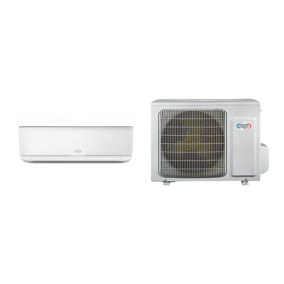
- Page 1 TECHNICAL DATA & SERVICE MANUAL ECOWALL 9000 IU + ECOWALL 9000 OU UNIT MODELS : ECOWALL 12000 IU + ECOWALL 12000 OU SPLIT SYSTEM AIR CONDITIONER June...
-
Page 2: Table Of Contents
Service Manual Table of Contents Part : Technical Information ...............1 1. Summary ........................1 . S eci cations ......................2 e i ati n eet ......................2 erati n ara teri ti r e ..................4 2.3 a a it ariati n Rati A r ing t erat re ............4 ing an Heating Data... - Page 3 Service Manual 9. Maintenance ......................33 9.1 rr r e i t .......................33 9.2 r re f r ting ..................41 aintenan e f r n r a a f n ti n ..............57 10. Removal Procedure ..................59 10.1 Re re f n r nit ................59 10.2 Re re f...
-
Page 4: Part : Technical Information
Service Manual Part : Technical Information 1. Summary ECOWALL 9000 IU ECOWALL 12000 IU Outdoor Unit: ECOWALL 9000 OU ECOWALL 12000 OU Remote Controller: WiFi Technical Information... -
Page 5: N I E R E
Service Manual 2. Speci cations 2.1 Speci cation Sheet ECOWALL 12000 IU ECOWALL 9000 IU Rate tage 220-240 220-240 Rate ing a a it 2500 3200 Heating a a it 2800 3400 er In Heating er In rrent 3.99 Heating rrent 3.74... -
Page 6: R Nit
Service Manual ECOWALL 9000 OU ECOWALL 12000 OU f O t r nit H HAI ANDA O RESSOR H HAI ANDA O RESSOR an fa t rer/ ra e ar -B096zE190A -B096zE190A r Oi W68DA W68DA R tar R tar .R.A. - Page 7 Service Manual 2.2 Operation Characteristic Curve Heating 220V Conditions 220V Indoor: DB27°C/WB19°C Outdoor: DB35°C/WB24°C Indoor air flow: High Pipe length: 5m 230V 230V 240V Conditions Indoor: DB20°C/WB15°C 240V Outdoor: DB7°C/WB6°C Indoor air flow: High Pipe length: 5m 10 20 30 40 50 60 70 80 90 100 Compressor speed (rps) Compressor speed (rps) 2.3 Capacity Variation Ratio According to Temperature...
-
Page 8: T R Nit
Service Manual 2.4 Cooling and Heating Data Sheet in Rated Frequency re f ga pipe In et an t et pipe Rate nne ting in r an te perat re f eat an pee an pee n iti n( ) (DB/WB) ti n r nit anger... - Page 9 Service Manual 3. Outline Dimension Diagram 3.1 Indoor Unit Φ55 Φ55 09/12K Technical Information...
- Page 10 Service Manual 3.2 Outdoor Unit Technical Information...
-
Page 11: Refrigerant System Diagram
Service Manual 4. Refrigerant System Diagram Cooling and heating model Outdoor unit Indoor unit Gas pipe side Valve 4-Way valve Di s charge Heat Suction Accumlator exchanger Compressor (evaporator) Heat exchanger Liquid pipe (condenser) side Valve Strainer Capillary Strainer COOLING HEATING nne ti n pipe pe i ati n i pipe 1/4 (6... -
Page 12: Electrical Part
Service Manual 5. Electrical Part 5.1 Wiring Diagram Instruction Na e W ite Green per ap n ing ire YEGN /Green i et Orange N te per ap i eter ine fan pee an t e ing ang e f riz nta er f r t i Technical Information... - Page 13 Service Manual Indoor Unit 60000700097301 Technical Information...
- Page 14 Service Manual Outdoor Unit 600007000763 600007000687 e e iring iagra e t t ange it t n ti e p ea e refer t t e ne pp ie it t e nit. Technical Information...
- Page 15 Service Manual 5.2 PCB Printed Diagram Indoor Unit Top view Name Interface of health function live wire Live wire interface Interface of health function neutral wire(only for the model with this function) Neutral wire interface Fan motor interface of PG Fuse Communication interface Auto button...
- Page 16 Service Manual Outdoor Unit Top view Na e r iring ter ina Rea t r iring ter ina r fan iring ter ina er ina a i e e tri eater er ina e e tri eater er ina f 4- a n ing ire ni ati n ire Ne tra...
-
Page 17: Function And Control
Service Manual 6. Function and Control 6.1 Remote Controller Introduction Buttons on Remote Controller On/Off button Mode button Fan button ▲/ button Swing button Sleep button Temp button Turbo button I Feel button Timer button WiFi button WiFi Light button Icon Display on Remote Controller Temp. - Page 18 Service Manual 1. ON/OFF button Press this button to turn on the unit. Press this button again to turn off the unit. 2. MODE button Each time you press this button,a mode is selected in a sequence that goes from AUTO, COOL, DRY, FAN, and HEAT *, as the following: * Note: Only for models with heating function.
- Page 19 Service Manual 11. WIFI button Press " WiFi " button to turn on or turn off WiFi function. When WiFi function is turned on, the " WiFi " icon will be displayed on remote controller; Under status of unit off, press "MODE" and " WiFi " buttons simultaneously for 1s, WiFi module will restore to factory defaultset- ting.
-
Page 20: Re Te Ntr Er Ntr
Service Manual 6.2 Brief Description of Modes and Functions Indoor Unit 1.Basic function of system (1)Cooling mode (1) n er t i e fan an ing perate at etting tat . e perat re etting range i 16 30 (2) D ring a f n ti n f r nit r t e nit i t ppe... - Page 21 Service Manual (8)I feel control mode After ntr er re ei e I fee igna an a ient te perat re ent ntr er ntr er i r ing t t e a ient te perat re ent ntr er. (9)Entry condition for compulsory defrosting function W en t rn n t e nit n er eating e an...
-
Page 22: Ti N
Service Manual Outdoor Unit 1. Cooling mode: W r ing n iti n an pr W en in ient te perat re pre et nit enter int e. In r fan r fan an r tart perati n. r fan perate a r ing t et fan pee . - Page 23 Service Manual 7. Auto mode eter ine ntr er f ID . See ID gi f r etai . 8. 8 C heating Set te perat re i 8 . Di p a f ID i p a . n er t i air pre enti n f n ti n i ie e .
- Page 24 Service Manual Safety Precautions for Installing and Relocating the Unit: To ensure safety, please be mindful of the following precautions. Warnings 1. When installing or relocating the unit, be sure to keep the refrigerant circuit free from air or substances other than the speci ed refrigerant.
- Page 25 Service Manual Safety Operation of Flammable Refrigerant uali cation requirement for installation and maintenance man All the work men who are engaging in the refrigeration system should bear the valid certi cation awarded by the authoritative organization and the quali cation for dealing with the refrigeration system recognized by this industry. If it needs other technician to maintain and repair the appliance, they should be supervised by the person who bears the quali cation for using the ammable refrigerant.
-
Page 26: Part : Installation And Maintenance
Service Manual Part : Installation and Maintenance 7. Notes for Installation and Maintenance Safety Precautions: 10. If the power cord or connection wire is not long enough, please get the specialized power cord or connection wire Important! from the manufacture or distributor. Prohibit prolong the wire by yourself. - Page 27 Service Manual To ensure safety, please be mindful of the following precautions. When installing or relocating the unit, be sure to keep the refrigerant circuit free from air or substances other than the speci ed refrigerant. Any presence of air or other foreign substance in the refrigerant circuit will cause system pressure rise or compressor rupture, resulting in injury.
- Page 28 Service Manual Main Tools for Installation and Maintenance 1. Level meter, measuring tape 2. Screw driver 3. Impact drill, drill head, electric drill 4. Electroprobe 5. Universal meter 6. Torque wrench, open-end wrench, inner hexagon spanner 7. Electronic leakage detector 8.
-
Page 29: Installation
Service Manual 8. Installation 8.1 Installation Dimension Diagram Space to the wall Space to the wall At least 15cm At least 15cm Drainage pipe Installation and Maintenance... - Page 30 Service Manual Installation procedures Start installation Preparation before installation Read the requirements select installation Prepare tools for electric connection location Select indoor unit Select outdoor unit installation location installation location Install the support of outdoor unit Install wall-mounting (select it according to the actual situation) frame, drill wall holes Connect pipes of indoor Fix outdoor unit...
-
Page 31: N Ta Ati N Di En I N Diagra
Service Manual 8.2 Installation Parts-Checking 8.4 Requirements for electric connection 1. Safety Precaution Na e Na e t e e e tri afet reg ati n en in ta ing r nit Sea ing g t e nit. r nit Wrapping tape (2) A r ing t t e... - Page 32 Service Manual pe ifi ati n f ri e t e a e a t e p a ti 5. Connect the Pipe of Indoor Unit e pan i n parti e) an t en t e p a ti e pan i n parti e (1) Ai t e pipe int at t e...
- Page 33 Service Manual 7. Connect Wire of Indoor Unit 8. Bind up Pipe (1) Open t e pane re e t e n t e iring er an (1) Bin p t e nne ti n pipe p r an rain t en ta e n t e er.(A...
- Page 34 Service Manual 8.6 Installation of Outdoor unit Refer t t e f ing ta e f r ren ent f f r e e(N . ) 1. Fix the Support of Outdoor Unit(Select it according to He n t ia eter( ig tening t r the actual installation situation) 15 20...
- Page 35 Service Manual ater t et ant e p a e in ater in r er t rain 8.8 Check after Installation and Test in ig.27) operation 1. Check after Installation r ing t t e f ing re ire ent after fini in ta ati n.
- Page 36 Service Manual 9. Maintenance 9.1 Error Code List Di p a f O t Di p a f In r nit In i at r a 3 in In i at r Di p a ( ring i p a ring a f n ti n in ing ON 0.5 an O...
- Page 37 Service Manual Di p a f O t Di p a f In r nit In i at r a 3 in In i at r Di p a ( ring i p a ring a f n ti n in ing ON 0.5 an O D a -8 i e a...
- Page 38 Service Manual Di p a f O t Di p a f In r nit In i at r a 3 in In i at r Di p a ( ring i p a ring a f n ti n in ing ON 0.5 an O D a -8 i e a...
- Page 39 Service Manual Di p a f O t Di p a f In r nit In icat r a 3 in In icat r Di p a ( ring i p a ring a f ncti n in ing ON 0.5 an O D a -8 i e a in ing ON 0.5 an O...
- Page 40 Service Manual Di p a f O t Di p a f In r nit In icat r a 3 in In icat r Di p a ( ring i p a ring a f ncti n in ing ON 0.5 an O D a -8 i e a in ing ON 0.5 an O...
- Page 41 Service Manual Di p a f O t Di p a f In r nit In icat r a 3 in In icat r Di p a ( ring i p a ring a f ncti n in ing ON 0.5 an O D a -8 i e a in ing ON 0.5 an O...
- Page 42 Service Manual If malfunction occurs,corresponding code will display and the unit will resume normal until protection or malfunction disappears. Installation and Maintenance...
- Page 43 Service Manual Analysis or processing of some of the malfunction display: 1. Compressor discharge protection i e ca rtage f refrigerant c age f air fi ter p r enti ati n r air f w rt pa f r c n en er t e a n nc n en ing ga ( c a air water etc.) c age f capi ar a...
- Page 44 Service Manual 9.2 Procedure of Troubleshooting 1. Malfunction of Temperature Sensor F1, F2 ain etecti n p int I t e wiring ter ina etween t e te perat re en r an t e c ntr er r c ntacte I t ere rt circ it e t trip-...
- Page 45 Service Manual 2. Malfunction of Blocked Protection of IDU Fan Motor H6 ain etecti n p int I t e c ntr ter ina f PG t r c nnecte tig t I t e fee ac interface f PG t r c nnecte tig t e fan t r can t perate...
- Page 46 Service Manual (3) Malfunction of Protection of Jumper Cap C5 ain etecti n p int I t ere per cap n t e I t e per cap in erte c rrect an tig t per i t r i Detecti n circ it f t e ar i e ne a n r a...
- Page 47 Service Manual 4. Malfunction of Zero-crossing Inspection Circuit Malfunction of the IDU Fan Motor U8 ain etecti n p int In tant energizati n afte e-energizati n w i e t e capacit r i c arge e zer -cr etecti ncirc it f t e ar i e ne a n r a...
- Page 48 Service Manual 5. High Temperature and Overload Protection (AP1 below means control board of outdoor unit) E8 Start Normal protection, please use it Unit restarts If the outdoor ambient temperature is after improving the outdoor ambient normally higher than 53°C? temperature Improve the radiating environment of Unit restarts...
- Page 49 Service Manual (5) Malfunction of detecting plate(WIFI) JF Start check if the connection wire are correctly connected detecting Replace the plate with the same model Is malfunction eliminated Replace the mainboard with the same model The end Installation and Maintenance...
- Page 50 Service Manual Outdoor unit: (1) Capacitor charge fault (Fault with outdoor unit) (AP1 below refers to the outdoor control panel) ec P int t eter t c ec if t e tage etween ter ina an N n t e wiring ar i wit in 210 A 240 A .
- Page 51 Service Manual (2) IPM Protection, Out-of-step Fault, Compressor Phase Overcurrent (AP1 below refers to the outdoor control panel) ain c ec p int I t e c nnecti n etween c ntr pane AP1 an c r O P ec re e I t e c nnecti n in c rrect r er I t e tage inp t f t e...
- Page 52 Service Manual Energize and switch on Use AC voltmeter If the voltage Check the supply to measure the IPM protection between terminal L voltage and voltage between occurs after the and N on wiring machine has run for terminal L and N restore it to board XT is within a period of time?
- Page 53 Service Manual (3) High temperature and overload protection diagnosis (AP1 hereinafter refers to the control board of the outdoor unit) etect ient te perat re in n r a range Are t e r an in r fan perating n r a I t e eat i ipati n en ir n ent in i e an t i e t e nit g a t iagn...
- Page 54 Service Manual (4) Start-up failure (following AP1 for outdoor unit control board) etect W et er t e c r wiring i c nnecte c rrect I ti e f r c r t pping en a t iagn i pr ce Power on the unit Restart it up after Is stop time of the compressor...
- Page 55 Service Manual (5) Out of step diagnosis for the compressor (AP1 hereinafter refers to the control board of the outdoor unit) etect I t e re t I t e inp t tage t a t iagn i pr ce Out of step occurs in Out of step occurs once the operation...
- Page 56 Service Manual (6) Overload and air exhaust malfunction diagnosis (following AP1 for outdoor unit control board) etect I t e P c nnecte we r n t I P a age I refrigerant ea e a t iagn i pr ce 20 minutes after the complete unit is powered off...
- Page 57 Service Manual (7) Power factor correct or (PFC) fault (a fault of outdoor unit) (AP1 hereinafter refers to the control board of the outdoor unit) etect ec if t e react r ( ) f t e r nit an t e P capacit r are r a t iagn i pr ce...
- Page 58 Service Manual (8) Communication malfunction: (following AP1 for outdoor unit control board) etect I t ere an a age f r t e in r nit ar c nicati n circ it I c nicati n circ it a age Detect t e in r an r nit c nnecti n wire an in...
- Page 59 Service Manual (9) Malfunction of Overcurrent Protection ain etecti n p int I t e tage n ta e wit ct ati n I t e tage t w wit er a Har ware tr a f ncti n iagn i pr ce Start N r a...
- Page 60 Service Manual 9.3 Maintenance method for normal malfunction 1. Air Conditioner Cant be Started Up i e a Di cri inating (Air c n iti ner Stat ting w et er it e t p wer fai re. If e N p wer After energizati n perati n in icat r i nt rig t...
- Page 61 Service Manual 4. ODU Fan Motor Cant Operate i e ca Di cri inating (air c n iti ner tat ting nnect wire acc r ing t wiring iagra Wr ng wire c nnecti n ec t e wiring tat acc r ing t circ it re a wiring ter ina are c nnecte c nnecti n...
- Page 62 Service Manual 10. Removal Procedure Caution: discharge the refrigerant 10.1 Removal Procedure of Indoor Unit completely before removal. Step Procedure 1. Re e ter Pane Open t e pane . en t e c a p wn in t e fig an t en p t e eft fi ter an rig t fi er...
- Page 63 Service Manual Step Procedure Pane 3. Re e pane Di p a Screw Open t e fr nt pane eparate t e pane r tati n aft fr t e gr e fi ing t e fr nt pane an t en re e t e fr nt r nt pane pane .
- Page 64 Service Manual Step Procedure a generat r 6. Re e e ectric Screw en t e c nnecti n c a p etween a generat r an e ectric an t en re e t e c generat r. E ectric Step n ing te perat re en...
- Page 65 Service Manual Step Procedure 7. Re e e ap rat r a e 3 crew ing e ap rat r a Screw nnecti n pipe c a p At t e ac f t e nit en t e c a p c nnecti n pipe c a p an t en e t e c nnecti n pipe c a p.
- Page 66 Service Manual Step Procedure 8. Re t r an cr e 3 crew t r c a p an t en re e t e t r c a p. t r c a p Screw e t e at t e c nnecti n p ace f a e an t r ift t e an cr...
- Page 67 Service Manual 10.2 Removal Procedure of Outdoor Unit Steps Procedure 1.Remove big handle Before disassamble. Remove the screws fixing handle、valve big handle cover and then remove them. valve cover 2. Remove top cover top cover Remove the screws fixing top panel and then remove the top panel.
- Page 68 Service Manual Step Procedure 3.Remove grille 、protective grille and front panel Remove connection screws between the front grille and the front panel. Then remove the front grille. Remove connection screws connecting the front protective panel with the chassis and the motor support, and grille then remove the front panel.
- Page 69 Service Manual Step Procedure 6.Remove motor and motor support Remove the screws fixing motor and then remove the motor. Remove the screws fixing motor support and then remove the motor support. motor support motor 7.Remove electric box assy Remove the screws fixing electric box assy; cut off electric box assy the tieline;...
- Page 70 Service Manual Step Procedure 9.Remove 4-way valve assy and capillary sub-assy Unsolder the welding joints connecting the 4-way valve assy with capillary sub-assy, compressor and condenser; remove the 4-way valve. 4-way valve assy Note: Before unsoldering the welding joint, wrap the 4-way valve with a wet cloth completely to avoid damage to the valve caused by high temperature.
- Page 71 Service Manual 1.Remove big handle Before disassembly. Remove the connection screw fixing the big handle and then remove the handle. handle 2. Remove top cover top panel Remove connection screws connecting the top cover plate with the front panel and the right side plate, and then remove the top panel.
- Page 72 Service Manual 3.Remove grille axial flow blade and front panel Remove connection screws between the front grille and the front panel. Then remove the front grille. Remove connection screws connecting the front panel with the chassis and the motor support, and then remove the front panel.
- Page 73 Service Manual 6.Remove 4-way valve assy Unscrew the fastening nut of the 4-way valve 4-way valve assy assy coil and remove the coil. Wrap the 4 way Valve Assy with wet cotton and unsolder the 4 weld spots connecting the 4-way valve assy to take it out.(Note: Refrigerant shouldbe discharged firstly.) Welding process should be as quickly as possible and keep wrapping...
- Page 74 Service Manual 9.Remove valves Remove the 2 screws fixing the gas valve and unsolder the welding point between the gas valve and the air-return pipe to remove the gas valve. Remove the 2 screws fixing the liquid valve and unsolder the welding joint connecting the liquid valve to the Y-type pipe to remove the liquid valve.
- Page 75 Service Manual Appendix: Appendix 1: Reference Sheet of Celsius and Fahrenheit Conversion formula for Fahrenheit degree and Celsius degree: Tf=Tcx1.8+32 Set temperature a ren eit a ren eit a ren eit i p a a ren eit i p a a ren eit i p a a ren eit...
- Page 76 Service Manual Appendix 3: Pipe Expanding Method Pipe Note: Improper pipe expanding is the main cause of refrigerant leakage.Please Pipe cutter expand the pipe according to the following steps: Leaning Uneven Burr t t e pip t e pipe engt acc r ing t t e i tance f in r nit an r nit.
- Page 77 Service Manual Appendix 4: List of Resistance for Temperature Sensor Resistance Table of Ambient Temperature Sensor for Indoor and Outdoor (15K) e p( ) Re i tance( e p( ) Re i tance( e p( ) Re i tance( e p( ) Re i tance( 138.1 18.75...
- Page 78 Service Manual Resistance Table of Tube Temperature Sensors for Outdoor and Indoor (20K) e p( ) Re i tance( e p( ) Re i tance( e p( ) Re i tance( e p( ) Re i tance( 181.4 25.01 5.13 1.427 171.4 23.9...
- Page 79 Service Manual Resistance Table of Discharge Temperature Sensor for Outdoor (50K) e p( ) Re i tance( e p( ) Re i tance( e p( ) Re i tance( e p( ) Re i tance( 853.5 18.34 4.75 799.8 93.42 17.65 4.61 89.07...
- Page 80 ARGOCLIMA SPA - Via Alfeno Varo, 35 - Alfianello (BS) Italy...
Need help?
Do you have a question about the ECOWALL 12000 IU and is the answer not in the manual?
Questions and answers