Table of Contents
Advertisement
SERVICE MANUAL
Ver. 1.0 2008.05
• HCD-EH25 is the amplifi er, USB, CD player,
tape deck and tuner section in CMT-EH25.
• HCD-EH26 is the amplifi er, USB, CD player,
tape deck and tuner section in CMT-EH26.
• "WALKMAN" and "WALKMAN" logo are registered
trademarks of Sony Corporation.
• MPEG Layer-3 audio coding technology and patents
licensed from Fraunhofer IIS and Thomson.
Amplifier section
European and Russian models:
DIN power output (rated):
4 + 4 watts (4 ohms at 1 kHz, DIN)
Continuous RMS power output
(reference): 5 + 5 watts (4 ohms at
1 kHz, 10% THD)
Music power output (reference):
7 + 7 watts (4 ohms at 1 kHz, 10%
THD)
Other models:
DIN power output (rated):
4 + 4 watts (4 ohms at 1 kHz, DIN)
Continuous RMS power output
(reference): 5 + 5 watts (4 ohms at
1 kHz, 10% THD)
Inputs:
AUDIO IN (stereo mini jack):
voltage 800 mV, impedance
47 kilohms
(USB) port: Type A, maximum
current 500 mA
Outputs:
PHONES (stereo mini jack): accepts
headphones of 8 ohms or more
SPEAKER: accepts impedance of
4 ohms
Sony Corporation
9-889-152-01
2008E05-1
Audio Business Group
©
2008.05
Published by Sony Techno Create Corporation
HCD-EH25/EH26
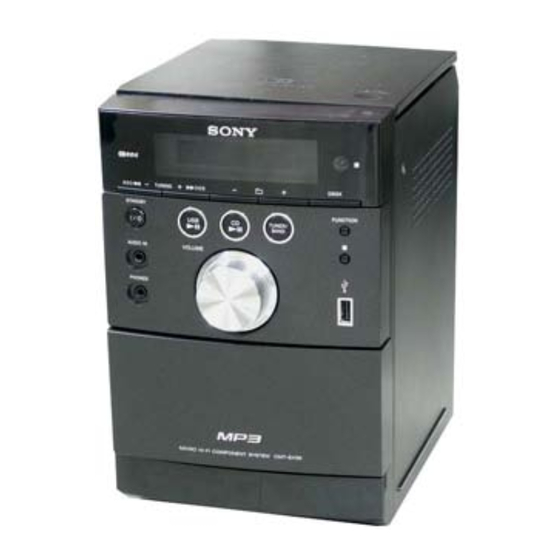
Photo: HCD-EH26
CD
Section
TAPE
Section
SPECIFICATIONS
USB section
Supported bit rate
MP3 (MPEG 1 Audio Layer-3):
32 – 320kbps, VBR
Sampling frequencies
MP3 (MPEG 1 Audio Layer-3):
32/44.1/48 kHz
CD player section
System: Compact disc and digital audio
system
Laser Diode Properties
Emission Duration: Continuous
Laser Output*: Less than 44.6µW
* This output is the value measurement
at a distance of 200mm from the
objective lens surface on the Optical
Pick-up Block with 7mm aperture.
Frequency response: 20 Hz – 20 kHz
Signal-to-noise ratio: More than 90 dB
Dynamic range: More than 90 dB
Tape deck section
Recording system: 4-track 2-channel, stereo
Tuner section
FM stereo, FM/AM superheterodyne tuner
Model Name Using Similar Mechanism
Base Unit Name
Optical Pick-up Name
Model Name Using Similar Mechanism
Tape Transport Mechanism Type
FM tuner section:
Tuning range:
87.5 − 108.0 MHz (50 kHz step)
Antenna: FM lead antenna
Intermediate frequency: 10.7 MHz
AM tuner section:
Tuning range
Korean model:
531 − 1,602 kHz (with 9 kHz tuning
interval)
530 − 1,610 kHz (with 10 kHz tuning
interval)
Other models:
531 − 1,602 kHz (9 kHz step)
Antenna: AM loop antenna
Intermediate frequency: 450 kHz
General
Power requirements
Korean model: 220 V AC, 60 Hz
Other models: 230 V AC, 50/60 Hz
Power consumption: 27 watts
Dimensions (w/h/d) (excl. speakers):
Approx. 155 × 241 × 224.6 mm
Mass (excl. speakers): Approx. 2.2 kg
Design and specifications are subject to
change without notice.
COMPACT DISC DECK RECEIVER
AEP Model
HCD-EH25/EH26
UK Model
Russian Model
Korean Model
HCD-EH25
NEW
BU-K8BD90-WOD
KSM-213CDP
HCD-EH10
MF-EH10
Advertisement
Table of Contents

Related Manuals for Sony HCD-EH26


Summarization of Contents
SERVICING NOTES
Handling Optical Pick-up Block
Precautions for handling optical pick-up blocks and flexible boards to prevent damage.
Laser Diode Emission Check
Procedure for checking laser diode emission safely from a distance.
Unleaded Solder Characteristics
Properties of unleaded solder and precautions for its use.
Laser Diode and Focus Search Operation
Method for checking laser diode emission and focus search.
GENERAL INFORMATION
Unit and Remote Controls Guide
Identifies and explains the functions of buttons on the unit and remote control.
System Display Information
Explains the indicators and information shown on the system display.
DISASSEMBLY PROCEDURES
Disassembly Flow Overview
Outlines the sequence for disassembling the unit.
Rear Cabinet Block Disassembly
Step-by-step guide to removing the rear cabinet.
Front, Top Cabinet, and Main Board Disassembly
Instructions for disassembling front, top cabinet, and main board.
Tape Mechanism and Cassette Lid Disassembly
Steps for removing the tape mechanism and cassette lid.
Base Unit Block Disassembly
Guide for disassembling the base unit block.
Optical Pick-up Block Disassembly
Instructions for disassembling the optical pick-up block.
TEST MODES AND ERROR CODES
Cold Reset Procedure
Clears memory and resets the unit to initial conditions.
Panel Test Mode Operation
Activates panel test mode to check display and version information.
Tuner Step Change (Korean Models)
Adjusts the AM tuning interval between 9 kHz and 10 kHz.
CD Service Mode Operation
Allows adjustment of SLED and laser power for the optical pick-up.
CD Error Code Display and Meanings
Displays and explains optical pick-up system errors and their codes.
MECHANICAL ADJUSTMENTS
Record/Playback Head Azimuth Adjustment
Procedure for adjusting head azimuth for optimal playback.
ELECTRICAL ADJUSTMENTS
AM Voltage and Tracking Adjustment
Adjusts AM VT voltage and tracking for optimal reception.
FM Voltage and Tracking Adjustment
Adjusts FM VT voltage and tracking for optimal reception.
FM Detector Adjustment
Adjusts the FM detector for optimal tuning and distortion.
CD Section Focus Bias Check
Checks focus bias using an eye pattern for proper CD playback.
FM Tune Level Check
Checks FM signal reception levels and TUNED indicator status.
SYSTEM DIAGRAMS
CD Servo Section Block Diagram
Illustrates the signal flow and components of the CD servo system.
Tuner and USB Section Block Diagram
Shows the signal path and components for the tuner and USB functions.
Main and Power Supply Section Block Diagram
Depicts the main processing and power supply circuitry.
WIRING AND SCHEMATIC NOTES
Printed Wiring Board Conventions
Explains symbols and markings used on printed wiring boards.
Schematic Diagram Conventions
Explains symbols, notations, and measurement conditions for schematics.
Circuit Board Location Diagram
Shows the physical layout and connection points of the main circuit boards.
PRINTED WIRING BOARDS
CD Board Layout
Shows the layout of components and traces on the CD board.
USB Board Layout
Shows the layout of components and traces on the USB board.
MAIN Board Layout
Shows the layout of components and traces on the main board.
PANEL Board Layout
Shows the layout of components and traces on the panel board.
PT-VBUS Board Layout
Shows the layout of components and traces on the PT-VBUS board.
SCHEMATIC DIAGRAMS
CD Board Schematic
Detailed circuit diagram for the CD board.
USB Board Schematic
Detailed circuit diagram for the USB board.
MAIN Board Schematic (1/3)
Detailed circuit diagram for the main board, part 1.
MAIN Board Schematic (2/3)
Detailed circuit diagram for the main board, part 2.
MAIN Board Schematic (3/3)
Detailed circuit diagram for the main board, part 3.
Waveform Examples
Displays example waveforms for various test points and modes.
PANEL Board Schematic
Detailed circuit diagram for the panel board.
PT-VBUS Board Schematic
Detailed circuit diagram for the PT-VBUS board.
IC BLOCK DIAGRAMS
CD/USB Board IC Block Diagrams
Block diagrams for ICs on the CD and USB boards.
IC401 BA5826SFP-E2 Block Diagram
Block diagram for the BA5826SFP-E2 IC.
IC103, IC105, IC301 Block Diagrams
Block diagrams for IC103, IC105, and IC301.
IC401 BD3881FV Block Diagram
Block diagram for the BD3881FV IC.
IC451, 452 NJM2521M Block Diagram
Block diagrams for the NJM2521M ICs.
IC801 LV23003VA Block Diagram
Block diagram for the LV23003VA IC.
IC861 PT2579SN Block Diagram
Block diagram for the PT2579SN IC.
PANEL Board IC Block Diagrams
Block diagrams for ICs on the PANEL board.
IC709 PST3542UL Block Diagram
Block diagram for the PST3542UL IC.
PT-VBUS Board IC901 Block Diagram
Block diagram for the PQ1CG2032FZ IC on the PT-VBUS board.
IC PIN FUNCTION DESCRIPTIONS
CD Board IC101 Pin Functions
Details pin names, I/O, and descriptions for the CD-MP3 Processor IC101.
CD Board IC101 Pin Functions (Continued)
Continues pin function details for IC101, covering pins 57-100.
USB Board IC101 Pin Functions
Details pin functions for the USB Controller IC101.
USB Board IC101 Pin Functions (Continued)
Continues pin function details for USB Controller IC101, pins 63-64.
PANEL Board IC701 Pin Functions
Details pin functions for the System Controller IC701 on the PANEL board.
PANEL Board IC701 Pin Functions (Continued)
Continues pin function details for IC701, covering pins 65-100.
EXPLODED VIEWS
Overall Section Exploded View
Exploded view showing the overall assembly of the unit.
Front Cabinet Section Exploded View
Exploded view detailing the front cabinet components and their assembly.
Top Cabinet Section Exploded View
Exploded view showing the top cabinet components and their assembly.
Base Unit Section Exploded View
Exploded view of the base unit, including optical pick-up and motors.
ELECTRICAL PARTS LIST
CD Section Parts List
Comprehensive list of electrical parts for the CD section.
CD/MAIN Section Parts List
List of electrical parts for CD and MAIN sections.
MAIN Section Parts List (Capacitors)
List of capacitors used in the MAIN section.
MAIN Section Parts List (Components)
List of various components in the MAIN section.
MAIN/PANEL Section Parts List
List of electrical parts for MAIN and PANEL sections.
MAIN/PANEL Section Parts List (Resistors/Switches)
List of resistors and switches for MAIN/PANEL sections.
PANEL Section Parts List (Components)
List of various components in the PANEL section.
PANEL/PT-VBUS Section Parts List
List of electrical parts for PANEL and PT-VBUS sections.
PT-VBUS/USB Section Parts List
List of electrical parts for PT-VBUS and USB sections.
Miscellaneous and Accessory Parts
Lists miscellaneous and accessory parts for the unit.
REVISION HISTORY
Revision Log
Records the version history and changes made to the manual.
Need help?
Do you have a question about the HCD-EH26 and is the answer not in the manual?
Questions and answers