Table of Contents
Advertisement
SERVICE MANUAL
Ver 1.5 2003.08
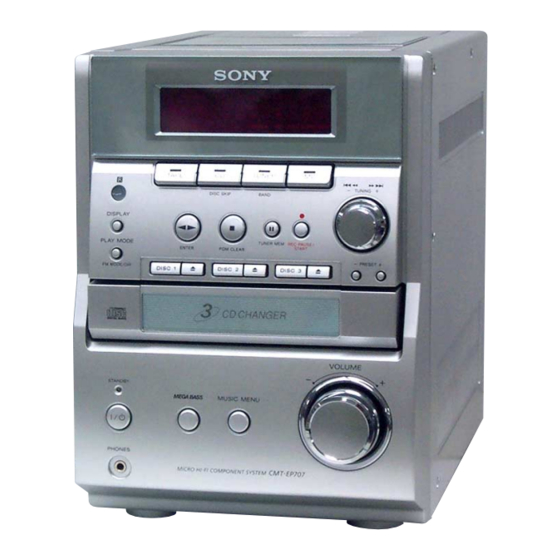
HCD-EP707 is the amplifier, CD
player, tape deck and tuner section
in CMT-EP707.
AUDIO POWER SPECIFICATIONS:
(U.S.A. model only)
POWER OUTPUT AND TOTAL
HARMONIC DISTORTION:
with 4 Ω loads both channels driven, from 120
- 10,000 Hz; rates 15 W per channel minimum
RMS power, with no more than 10% total
harmonic distortion from 250 mW to rated
output.
Amplifier section
Canadian model:
Continuous RMS power output (reference)
15 + 15 W
(4 Ω at 1 kHz, 10% THD)
European model:
DIN power output (rated) 12 + 12 W
(4 Ω at 1 kHz, DIN)
Continuous RMS power output (reference)
15 + 15 W
(4 Ω at 1 kHz, 10% THD)
Music power output (reference)
38 + 38 W
Other model:
The following measured at AC 230 V or AC 120 V,
50/60 Hz
DIN power output (rated) 12 + 12 W
(4 Ω at 1 kHz, DIN)
Continuous RMS power output (reference)
15 + 15 W
(4 Ω at 1 kHz, 10% THD)
Inputs
MD IN (phono jacks):
voltage 450 mV,
impedance 47 kilohms
Outputs
PHONES:
Accepts headphones of
(stereo mini jack)
8 Ω or more
SPEAKER:
Accepts impedance of 8 to
16 Ω
Sony Corporation
9-874-043-06
2003H05-1
Home Audio Company
C 2003.08
Published by Sony Engineering Corporation
HCD-EP707
Model Name Using Similar Mechanism
CD
Section
CD Mechanism Type
Model Name Using Similar Mechanism
TAPE
Section
Tape Transport Mechanism Type
SPECIFICATIONS
CD player section
System
Compact disc and digital
audio system
Laser
Semiconductor laser
(λ=780 nm)
Emission duration:
continuous
Frequency response
20 Hz - 20 kHz (±0.5 dB)
OPTICAL DIGITAL OUT
(Square optical connector jack, rear panel)
Wavelength
660 nm
Tape player section
Recording system
4-track 2-channel stereo
Frequency response
50 - 13 000 Hz (±3 dB),
using Sony TYPE I
cassette
Tuner section
FM stereo, FM/AM superheterodyne tuner
FM tuner section
Tuning range
87.5 - 108.0 MHz
Antenna
FM lead antenna
Antenna terminal (Except for European model)
75 Ω coaxial
Intermediate frequency
10.7 MHz
AM tuner section
Tuning range
Pan-American model:
530 - 1 710 kHz
(with the interval set at
10 kHz)
531 - 1 710 kHz
(with the interval set at
9 kHz)
European model:
531 -1 602 kHz
(with the interval set at
9 kHz)
COMPACT DISC DECK RECEIVER
US Model
Canadian Model
AEP Model
UK Model
Australian Model
NEW
CMCJ-0132
HCD-EP505
CRL4349
Other models:
531 - 1 602 kHz
(with the interval set at
9 kHz)
530 - 1 710 kHz
(with the interval set at
10 kHz)
Antenna
AM loop antenna
Intermediate frequency
450 kHz
General
Power requirements
North American model :
120 V AC, 60 Hz
Other models:
230 V AC, 50/60 Hz
Power consumption
European model:
38 W
0.5 W (in the standby
mode)
Other models:
38 W
Dimensions (w/h/d):
Approx. 180 × 246 × 335 mm
Mass:
Approx. 5.0 kg
Supplied accessories:
AM loop antenna (1)
Remote Commander (1)
Batteries (2)
FM lead antenna (1)
(Except for European
model)
Design and specifications are subject to change
without notice.
Advertisement
Table of Contents

Related Manuals for Sony HCD-EP707


Summary of Contents for Sony HCD-EP707
-
Page 1: Specifications
SERVICE MANUAL US Model Canadian Model Ver 1.5 2003.08 AEP Model UK Model Australian Model HCD-EP707 is the amplifier, CD player, tape deck and tuner section in CMT-EP707. Model Name Using Similar Mechanism Section CD Mechanism Type CMCJ-0132 Model Name Using Similar Mechanism... -
Page 2: Leakage Test
OPERATION. REPLACE THESE COMPONENTS WITH DE FONCTIONNEMENT. NE REMPLACER CES COM- SONY PARTS WHOSE PART NUMBERS APPEAR AS POSANTS QUE PAR DES PIÈCES SONY DONT LES SHOWN IN THIS MANUAL OR IN SUPPLEMENTS PUB- NUMÉROS SONT DONNÉS DANS CE MANUEL OU LISHED BY SONY. -
Page 3: Table Of Contents
HCD-EP707 Ver 1.1 TABLE OF CONTENTS SERVICING NOTES ..........4 GENERAL ..............5 DISASSEMBLY 3-1. Disassembly Flow ............6 3-2. Side (Panel) ..............7 3-3. Top Cabinet Section ............7 3-4. Tape Mechanism Deck (CRL4349) ........ 8 3-5. Front Panel Section ............8 3-6. -
Page 4: Servicing Notes
HCD-EP707 Ver 1.1 SECTION 1 SERVICING NOTES NOTE FOR TRANSPORTING A SET NOTES ON HANDLING THE OPTICAL PICK-UP After repair is completed, be sure to attach EP707 (SAFETY) BLOCK OR BASE UNIT (STRIP) (Part No. 4-244-664-01) and EP707 (STUD) (Part No. 4-... -
Page 5: General
HCD-EP707 SECTION 2 GENERAL This section is extracted from instruction manual. LOCATION OF CONTROLS – Front Panel – Main unit ALPHABETICAL ORDER BUTTON DESCRIPTIONS @/1 (power) w; A – M Cassette compartment 5 . m (go back) qs CD 3 M >... -
Page 6: Disassembly
HCD-EP707 SECTION 3 DISASSEMBLY • This set can be disassembled in the order shown below. 3-1. DISASSEMBLY FLOW 3-2. SIDE (PANEL) (Page 7) 3-3. TOP CABINET SECTION 3-9. POWER AMP BOARD (Page 7) (Page 10) 3-4. TAPE MECHANISM DECK 3-6. MAIN BOARD 3-5. -
Page 7: Side (Panel)
HCD-EP707 Note: Follow the disassembly procedure in the numerical order given. 3-2. SIDE (PANEL) 1 three screws 2 three screws (KTP3 × 8) (KTP3 × 8) 3 screw 8 side (panel) (R) (BVTP3 × 10) 5 three screws (KTP3 × 8) -
Page 8: Tape Mechanism Deck (Crl4349)
HCD-EP707 3-4. TAPE MECHANISM DECK (CRL4349) 2 tape mechanism deck (CRL4349) 4 four screws (BVTP3 × 10) 3-5. FRONT PANEL SECTION 3 connector 7 two screws (CON203) (BVTP3 × 12) 3 connector (CON205) 3 connector (CON211) 1 Remove a solder. -
Page 9: Main Board
HCD-EP707 3-6. MAIN BOARD 2 connector (CON211) 2 connector 2 connector (CON214) 2 connector (CON203) (CON205) 2 connector 2 connector (CON215) (CON216) AEP, UK 2 connector (CON207) 4 screw (BTP2.6 × 8) 3 two screws (BVTP3 × 12) 5 antenna jack cover 6 two screws (BVTT2 ×... -
Page 10: Regulator Board
HCD-EP707 3-8. REGULATOR BOARD 2 two screws (BVTP3 × 8) 1 connector (CON810) 5 Remove twelve solders. 6 regulator board regulator board 3 three claws (bottom side view) 3-9. POWER AMP BOARD 3 rear (cover) 6 four screws (BVTP3 × 8) -
Page 11: Cover
HCD-EP707 3-10. COVER 2 cover 1 two screws 1 two screws... -
Page 12: Drawer
HCD-EP707 3-11. DRAWER -bottom view- lever (slider-2) lever (slider-2) lever (slider-2) front rear 1 Slide the lever (slider-2) 2 Slide the lever (slider-2) in the direction of arrow A , in the direction of arrow B , at the full. -
Page 13: Belt (Gray/Black)
HCD-EP707 3-12. BELT (GRAY/BLACK) 1 belt (gray) 2 belt (black) 3-13. OPTICAL BLOCK 1 two screws 2 arm 3 carriage 0 cushion 4 four screws 9 two cushions 5 four washers 8 two cushions qa optical block 7 flexible cable... -
Page 14: Electrical Adjustments
HCD-EP707 SECTION 4 ELECTRICAL ADJUSTMENTS PRECAUTION TUNER SECTION 0 dB=1 µV 1. Setting MEGA BASS switch : OFF [AM] Setting: Function: TUNER TAPE DECK SECTION 0 dB=0.775 V TUNER/BAND switch: AM Test tape Put the lead-wire AM RF signal antenna close to... - Page 15 HCD-EP707 ): AEP, UK models Adjustment Location and Connecting Points AM IF ADJUSTMENT – MAIN BOARD (Component Side) – Adjust for a maximum reading on level meter IFT205 450 kHz L203 AM FREQUENCY COVERAGE ADJUSTMENT FM Tracking Adjustment VC202 Adjustment Part Frequency Display Reading on Digital Voltmeter...
-
Page 16: Diagrams
HCD-EP707 SECTION 5 DIAGRAMS 5-1. BLOCK DIAGRAM – TUNER Section – (AEP, UK) CF205 4.332MHz RCLK RCLK BUFFER (Page 19) RDATA Q208 VC202 RDS DECODER RDAT L203 IC203 FM RF CF203 L203, VC202 FM TRACKING FMRF OUT FM DET DET OUT... -
Page 17: Block Diagram - Tape Deck Section
HCD-EP707 5-2. BLOCK DIAGRAM – TAPE DECK Section – RL-CH (Page 18) RR-CH R-CH AMP GAIN CONTROL Q256 R-CH MUTING Q243 AMP GAIN CONTROL Q242 R-CH R-CH HPRE201 (1/2) (RECORD/PLAYBACK) OUT1 TL-CH (Page 18) TR-CH L-CH R-CH TAPE TYPE R-CH... -
Page 18: Block Diagram - Main Section
HCD-EP707 5-3. BLOCK DIAGRAM – MAIN Section – CON204 RL-CH LOUT (Page 17) RR-CH R-CH MD IN R-CH ROUT R-CH INPUT SELECT SWITCH, LIN4 ELECTRICAL VOLUME POWER AMP OUT_L IC207 TL-CH (Page 17) LIN3 SP801 MUTING MUTING – TR-CH R-CH... -
Page 19: Block Diagram - Display/Power Supply Section
HCD-EP707 5-4. BLOCK DIAGRAM – DISPLAY/POWER SUPPLY Section – B+ SWITCH CD BLOCK B+ Q210, 211 CD-EN, TU-EN, D212 MUTING CD-EN (Page 18) TUNER B+ MAIN +5V REGULATOR B+ SWITCH POWER FM/AM PLL B+ Q205 Q206, 207 TRANSFORMER TR800 TU-EN... -
Page 20: Note For Printed Wiring Boards And Schematic Diagrams
HCD-EP707 5-5. NOTE FOR PRINTED WIRING BOARDS AND SCHEMATIC DIAGRAMS • Waveforms – MAIN Board – – DISPLAY Board – Note on Printed Wiring Boards: Note on Schematic Diagram: 1 IC201 ws XOUT (TUNER mode) 3 IC203 qf XO qa IC101 qa X2 •... -
Page 21: Printed Wiring Boards - Main Section
HCD-EP707 • Semiconductor Location 5-6. PRINTED WIRING BOARDS – MAIN Section – • See page 20 for Circuit Boards Location. Ref. No. Location CON219 D201 D202 (Page 28) (Page 26) (Page 26) D203 ∗ ∗ DISPLAY DISPLAY REGULATOR SUPPLIED WITH THE... -
Page 22: Schematic Diagram - Main Section (1/2)
HCD-EP707 5-7. SCHEMATIC DIAGRAM – MAIN Section (1/2) – • • See page 20 for Waveforms. See page 30 for IC Block Diagrams. MAIN BOARD (1/2) (AEP, UK) L203, VC202 L204 FM TRACKING FM FREQUENCY COVERAGE Q248 – 251 LED DRIVE... -
Page 23: Schematic Diagram - Main Section (2/2)
HCD-EP707 5-8. SCHEMATIC DIAGRAM – MAIN Section (2/2) – • • See page 20 for Waveform. See page 30 for IC Block Diagrams. MAIN BOARD (2/2) <0> {4.5} <0> <0.4> <0.9> {4.5} 1500P {1.7} {1.7} 2.2U <0> <0.9> REC/PB POWER AMP {1.7}... -
Page 24: Printed Wiring Boards - Power Amp Section
HCD-EP707 5-9. PRINTED WIRING BOARDS – POWER AMP Section – • See page 20 for Circuit Boards Location. • Semiconductor Location Ref. No. Location POWER AMP BOARD Q701 Q702 Q703 Q704 U700 U701 U700 (Page 28) REGULATOR BOARD CON801 REGULATOR... -
Page 25: Schematic Diagram - Power Amp Section
HCD-EP707 5-10. SCHEMATIC DIAGRAM – POWER AMP Section – POWER AMP BOARD C624 REGULATOR 0.1UF BOARD R635 CON808 25.6 (Page 29) 100PF 22.8 R711 13.2 2.7k CE619 SPEAKER JACK 200UF Q703 24.5 DTC343TS BOARD R712 2.7k MAIN 13.2 BOARD CON800... -
Page 26: Printed Wiring Boards - Display Section
HCD-EP707 5-11. PRINTED WIRING BOARDS – DISPLAY Section – • See page 20 for Circuit Boards Location. • Semiconductor Location (Page 21) (Page 21) (Page 21) Ref. No. Location MAIN BOARD MAIN BOARD MAIN BOARD D101 CON205 CON203 CON211 D102... -
Page 27: Schematic Diagram - Display Section
HCD-EP707 5-12. SCHEMATIC DIAGRAMS – DISPLAY Section – • See page 20 for Waveform. DISPLAY BOARD FLUORESCENT INDICATOR TUBE 1.2k 1.5k 1.8k 2.7k 3.3k 5.6k IC102 EEPROM 0.022U TUNING + TEST DISPLAY TAPE PLAY MODE TUNER DISC SKIP BAND FM MODE/DIR TUNING −... -
Page 28: Printed Wiring Boards - Regulator Section
HCD-EP707 5-13. PRINTED WIRING BOARDS – REGULATOR Section – • See page 20 for Circuit Boards Location. • Semiconductor Location Ref. No. Location D800 D801 REGULATOR BOARD D802 D803 D804 D805 CON808 D806 D807 D808 D809 D810 POWER D811 D812... -
Page 29: Schematic Diagram - Regulator Section
HCD-EP707 5-14. SCHEMATIC DIAGRAM – REGULATOR Section – REGULATOR BOARD 0.01 POWER BOARD 0.01 D802 – 805 (Page 25) RECT 0.01 POWER 0.01 0.01 BOARD D832, R834 +5V REGULATOR (Page 25) D806 – 809 RECT ∗ F803 0.01 2A 125V (US, CND) 0.01... - Page 30 HCD-EP707 • IC Block Diagrams – MAIN Board – IC204 BU4094BC IC207 PT2314 IC201 LC72131M-TL-M STROBE SERIAL IN 8 – STAGE 14 13 11 10 9 8 SHIFT REGISTER CLOCK PHASE DETECTOR TREBLE CHARGE PUMP 8 – BIT POWER LATCHES...
-
Page 31: Ic Pin Function Description
HCD-EP707 5-15. IC PIN FUNCTION DESCRIPTION • DISPLAY BOARD IC101 µPD780206GF-127-3BA (SYSTEM CONTROLLER) Pin No. Pin Name Description VDD3 — Power supply terminal (+4.2V) POWER Power on/off control signal output terminal “L”: standby, “H”: power on MUTE Muting on/off control signal output terminal “H”: active PLL-CE PLL chip enable signal output to the FM/AM PLL “H”... - Page 32 HCD-EP707 Pin No. Pin Name Description CAR HM Switch input from the CD block “H”: home position Switch input from the CD block Switch input from the CD block OP/CLS Switch input from the CD block “L”: When tray open/close completely SLD FW Switch input from the CD block “L”: when tray is close...
-
Page 33: Exploded Views
HCD-EP707 SECTION 6 EXPLODED VIEWS NOTE: • -XX and -X mean standardized parts, so they • Items marked “*” are not stocked since they The components identified by mark 0 or dotted line with mark 0 are may have some difference from the original are seldom required for routine service. -
Page 34: Front Panel Section
HCD-EP707 Ver 1.5 6-2. FRONT PANEL SECTION supplied supplied supplied supplied supplied supplied supplied supplied supplied supplied supplied not supplied (vol key board) supplied not supplied (headphone board) supplied with R216 supplied Ref. No. Part No. Description Remark Ref. No. -
Page 35: Top Cabinet Section
HCD-EP707 6-3. TOP CABINET SECTION Ref. No. Part No. Description Remark Ref. No. Part No. Description Remark 4-235-777-01 BELT (FR) 4-242-011-01 CASS LID SPRING 3-709-645-01 BELT SR 4-236-899-01 DAMPER 1-796-544-11 DECK, MECH (CRL4349) 4-236-906-01 CASS LID LATCH 4-242-009-01 TOP CABINET (US, CND) -
Page 36: Chassis Section
HCD-EP707 Ver 1.2 6-4. CHASSIS SECTION AEP, UK not supplied (speaker jack board) CD section F804 not supplied F803 supplied TR800 not supplied not supplied (switch board) The components identified by Les composants identifiés par une mark 0 or dotted line with... -
Page 37: Cd Section
HCD-EP707 6-5. CD SECTION supplied supplied supplied supplied supplied supplied supplied Ref. No. Part No. Description Remark Ref. No. Part No. Description Remark 1-796-542-11 MECHANICAL, CD (CMCJ-0132) 4-243-505-01 BELT (GRAY) 4-243-504-01 BELT (BLACK) -
Page 38: Electrical Parts List
HCD-EP707 SECTION 7 ELECTRICAL PARTS LIST DISPLAY NOTE: The components identified by mark • Due to standardization, replacements in the • Items marked “*” are not stocked since they 0 or dotted line with mark 0 are parts list may be different from the parts speci- are seldom required for routine service. - Page 39 HCD-EP707 DISPLAY HEADPHONE MAIN Ref. No. Part No. Description Remark Ref. No. Part No. Description Remark R319 1-249-422-11 CARBON 2.7K 1/4W R137 1-249-437-11 CARBON 1/4W R320 1-249-422-11 CARBON 2.7K 1/4W R138 1-249-437-11 CARBON 1/4W R321 1-249-422-11 CARBON 2.7K 1/4W R139...
- Page 40 HCD-EP707 MAIN Ref. No. Part No. Description Remark Ref. No. Part No. Description Remark < CAPACITOR > C265 1-127-880-21 CERAMIC 0.022uF C266 1-130-483-00 MYLAR 0.01uF C201 1-162-205-31 CERAMIC 18PF C267 1-162-294-31 CERAMIC 0.001uF C205 1-162-294-31 CERAMIC 0.001uF C268 1-130-488-00 MYLAR 0.027uF...
- Page 41 HCD-EP707 MAIN Ref. No. Part No. Description Remark Ref. No. Part No. Description Remark CE214 1-126-961-11 ELECT 2.2uF CE277 1-126-933-11 ELECT 100uF (AEP, UK) CE215 1-126-933-11 ELECT 100uF CE278 1-126-933-11 ELECT 100uF (AEP, UK) CE280 1-126-963-11 ELECT 4.7uF CE281 1-126-963-11 ELECT 4.7uF...
- Page 42 HCD-EP707 MAIN Ref. No. Part No. Description Remark Ref. No. Part No. Description Remark IC210 8-759-576-76 IC TDA2822D013TR Q245 8-729-905-50 TRANSISTOR DTC343TS-TP Q246 8-729-905-50 TRANSISTOR DTC343TS-TP < TRANSFORMER > Q247 8-729-905-50 TRANSISTOR DTC343TS-TP IFT201 1-424-935-11 COIL (AM OSC) Q248 8-729-194-57 TRANSISTOR...
- Page 43 HCD-EP707 MAIN Ref. No. Part No. Description Remark Ref. No. Part No. Description Remark R256 1-249-421-11 CARBON 2.2K 1/4W R321 1-249-433-11 CARBON 1/4W R257 1-249-421-11 CARBON 2.2K 1/4W R323 1-249-426-11 CARBON 5.6K 1/4W R324 1-249-441-11 CARBON 100K 1/4W R258 1-249-425-11 CARBON 4.7K...
- Page 44 HCD-EP707 MAIN POWER AMP REGULATOR Ref. No. Part No. Description Remark Ref. No. Part No. Description Remark C704 1-130-495-00 MYLAR 0.1uF R382 1-249-429-11 CARBON 1/4W C705 1-130-495-00 MYLAR 0.1uF R383 1-249-429-11 CARBON 1/4W CE619 1-104-666-11 ELECT 220uF R384 1-249-417-11 CARBON...
- Page 45 HCD-EP707 REGULATOR SPEAKER JACK Ref. No. Part No. Description Remark Ref. No. Part No. Description Remark 0 C824 1-117-698-11 CERAMIC 680PF 250V D832 8-719-109-85 DIODE MTZJ-T-72-5.1B C832 1-102-129-00 CERAMIC 10000PF 10% D833 8-719-991-33 DIODE 1N4148TP D834 8-719-991-33 DIODE 1N4148TP C833...
- Page 46 HCD-EP707 Ver 1.4 SPEAKER JACK SWITCH VOL KEY Ref. No. Part No. Description Remark Ref. No. Part No. Description Remark MISCELLANEOUS < TERMINAL BOARD > ************** * SP801 1-537-240-21 TERMINAL BOARD (CHECKER IN) 1-500-712-11 CORE, FERRITE (SPEAKER (IMPEDANCE USE 4Ω))
- Page 47 HCD-EP707 US Model Canadian Model SERVICE MANUAL AEP Model UK Model Australian Model Ver 1.3 2003.03 SUPPLEMENT-1 File this supplement with the service manual. Subject: Addition of “DISASSEMBLY” and “ASSEMBLY” of CD Mechanism deck (SPM-03006) SERVICING NOTES After assembling the CD mechanism deck, check that the drawer can be operated as shown in the figure below.
- Page 48 HCD-EP707 DISASSEMBLY 3-14. CARRIAGE 1 After taking out drawer from chassis, overturn the drawer and place on a jig, to prevent scratches on the drawer. 2 On the left hand side of the drawer, has a gear call the bevel gear.
- Page 49 HCD-EP707 5 When bevel gear is turned anti clockwise, the upper pinion will in also turn 5 times. When the upper pinion turns, it will transport the upper carriage out from its original position. When the upper carriage moves to it’s max position (upper pinion turns 5 times) the lower carriage will drop down next.
- Page 50 HCD-EP707 ASSEMBLY • This set can be assembled in the order shown below. 1. ASSEMBLY FLOW CARRIAGE (Page 4) DRAWER (Page 8) Note: Follow the assembly procedure in the numerical order given. 2. CARRIAGE carriage bevel gear upper pinion...
- Page 51 HCD-EP707 1 Before assembling back carriage to the drawer, make sure that the bevel gear is not missing and properly fixed. 2 After assembling the bevel gear, turn the bevel gear in clockwise direction and turn it until the upper pinion starts to turn.
- Page 52 HCD-EP707 • Differentiate Carriage Cavities No. 1 No. 2 Note: Carriage having two punches is cavity No. 3. 4 When placing the carriage into the drawer, make sure the carriage is fixed underneath the star gear and the last teeth into the front teeth of the upper pinion.
- Page 53 HCD-EP707 5 Turn the bevel gear in a clockwise direction and the carriage will move to the back of the drawer. Pinion will turn 5 times. 6 After the carriage reaches to the back of the drawer, the front star gear will turn slightly, after that, the lower pinion will turn 5 times.
- Page 54 HCD-EP707 3. DRAWER drawer drawer ditch arm stopper B 1 Push the drawer in the direction of arrow to the chassis as shown in the figure above. claw A claw B 2 Uptilt the right side of the drawer and engage the ditch of the drawer with the claw A .
- Page 55 HCD-EP707 MEMO...
-
Page 56: Revision History
HCD-EP707 REVISION HISTORY Clicking the version allows you to jump to the revised page. Also, clicking the version at the upper right on the revised page allows you to jump to the next revised page. Ver. Date Description of Revision 2002.06...
Need help?
Do you have a question about the HCD-EP707 and is the answer not in the manual?
Questions and answers
Where does the thin spring wire with loops at each end go? It was loose inside the cd player mechanism and fell out while getting the faulty tray to open.