Table of Contents
Advertisement
SERVICE MANUAL
Ver. 1.0 2008.04
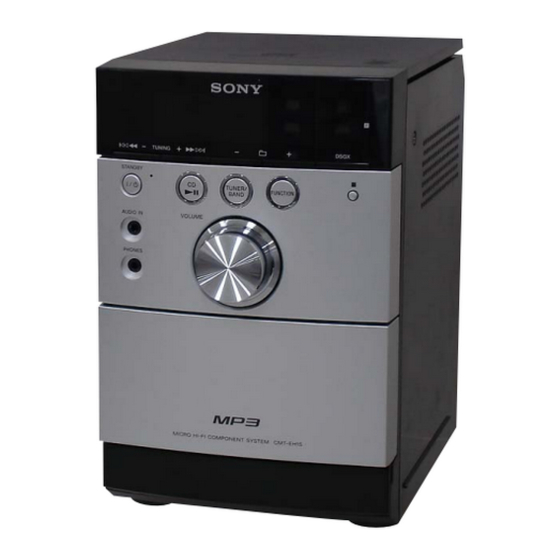
• HCD-EH15 is the amplifi er, CD player, tape
deck and tuner section in CMT-EH15.
Amplifier section
European and Russian models:
DIN power output (rated): 4 + 4 W (4 ohms at 1 kHz, DIN)
Continuous RMS power output (reference): 5 + 5 W (4 ohms at 1 kHz,
10% THD)
Music power output (reference): 7 + 7 W
Other models:
DIN power output (rated): 4 + 4 W (4 ohms at 1 kHz, DIN)
Continuous RMS power output (reference): 5 + 5 W (4 ohms at 1 kHz,
10% THD)
Inputs
AUDIO IN (stereo mini jack): Sensitivity 800 mV, impedance 47 kilohms
Outputs
PHONES (stereo mini jack): Accepts headphones with an impedance of
8 ohms or more
SPEAKER: Accepts impedance of 4 ohms
CD player section
System: Compact disc and digital audio system
Laser Diode Properties
Emission Duration: Continuous
Laser Output*: Less than 44.6μW
* This output is the value measurement at a distance of 200 mm from the
objective lens surface on the Optical Pick-up Block with 7 mm aperture.
Frequency response: 20 Hz
Signal-to-noise ratio: More than 90 dB
Dynamic range: More than 90 dB
Tape deck section
Recording system: 4-track 2-channel, stereo
Tuner section
FM stereo, FM/AM superheterodyne tuner
Antenna:
FM lead antenna
AM loop antenna
Sony Corporation
9-889-094-01
2008D05-1
Audio Business Group
©
2008.04
Published by Sony Techno Create Corporation
CD
Section
Tape
Section
SPECIFICATIONS
20 kHz
HCD-EH15
Canadian Model
Australian Model
Model Name Using Similar Mechanism
Base Unit Name
Optical Pick-up Name
Model Name Using Similar Mechanism
Tape Transport Mechanism Type
FM tuner section:
Tuning range
Canadian model: 87.5
108.0 MHz (100 kHz step)
Other models: 87.5
108.0 MHz (50 kHz step)
Intermediate frequency: 10.7 MHz
AM tuner section:
Tuning range
Canadian and Latin American models:
530
1,710 kHz (with 10 kHz tuning interval)
531
1,710 kHz (with 9 kHz tuning interval)
European and Russian models:
531
1,602 kHz (with 9 kHz tuning interval)
Australian model:
531
1,710 kHz (with 9 kHz tuning interval)
530
1,710 kHz (with 10 kHz tuning interval)
Other models:
531
1,602 kHz (with 9 kHz tuning interval)
530
1,610 kHz (with 10 kHz tuning interval)
Intermediate frequency: 450 kHz
General
Power requirements:
Canadian model: AC 120 V, 60 Hz
Mexican model: AC 120 V, 60 Hz
Eu
ropean and Russian models: AC 230 V, 50/60 Hz
Australian model: AC 230
240 V, 50/60 Hz
Argentine model: AC 220 V, 50/60 Hz
Korean model: AC 220 V, 60 Hz
Taiwan model: AC 120 V, 50/60 Hz
Other models: AC 110
120 or 220
240 V, 50/60 Hz
Adjustable with voltage selector
Power consumption: 25 W
Dimensions (w/h/d) (excl. speakers): Approx. 155 × 241 × 224.6 mm
Mass (excl. speakers): Approx. 2.2 kg
Design and specifications are subject to change without notice.
COMPACT DISC DECK RECEIVER
UK Model
E Model
Russian Model
NEW
BU-K8BD90-WOD
KSM-213CDP
NEW
MF-EH10
Advertisement
Table of Contents

Related Manuals for Sony HCD-EH15


Summary of Contents for Sony HCD-EH15
-
Page 1: Specifications
Canadian Model UK Model Ver. 1.0 2008.04 E Model Australian Model Russian Model • HCD-EH15 is the amplifi er, CD player, tape deck and tuner section in CMT-EH15. Model Name Using Similar Mechanism Base Unit Name BU-K8BD90-WOD Section Optical Pick-up Name... -
Page 2: Table Of Contents
LES DIAGRAMMES SCHÉMATIQUES ET LA LISTE DES PIÈCES SONT CRITIQUES POUR LA SÉCURITÉ DE FONC- TIONNEMENT. NE REMPLACER CES COM- POSANTS QUE PAR DES PIÈCES SONY DONT LES NUMÉROS SONT DON- NÉS DANS CE MANUEL OU DANS LES SUPPLÉMENTS PUBLIÉS PAR SONY. -
Page 3: Servicing Notes
HCD-EH15 SECTION 1 SERVICING NOTES MODEL IDENTIFICATION NOTES ON HANDLING THE OPTICAL PICK-UP – Rear Cabinet – BLOCK OR BASE UNIT The laser diode in the optical pick-up block may suffer electrostat- ic break-down because of the potential difference generated by the charged electrostatic load, etc. -
Page 4: General
HCD-EH15 SECTION 2 This section is extracted GENERAL from instruction manual. Basic Operations Adjusting the sound Listening to the radio Select “FM” or “AM. ” To adjust the volume Press TUNER/BAND repeatedly. Press VOLUME +/ (or turn the VOLUME control on ... -
Page 5: Other Operations
HCD-EH15 Other Operations Creating your own CD program Recording onto a tape (Program Play) Use a TYPE I (normal) tape only. You can record just the portions you like from a sound Use buttons on the remote to create your own program. -
Page 6: Disassembly
HCD-EH15 SECTION 3 DISASSEMBLY • This set can be disassembled in the order shown below. 3-1. DISASSEMBLY FLOW 3-2. REAR CABINET BLOCK (Page 6) 3-3. FRONT CABINET BLOCK, TOP CABINET BLOCK, MAIN BOARD (Page 7) 3-4. MF-EH10 (TAPE MECHANISM DECK), 3-5. -
Page 7: Front Cabinet Block, Top Cabinet Block, Main Board
HCD-EH15 3-3. FRONT CABINET BLOCK, TOP CABINET BLOCK, MAIN BOARD top cabinet block two screws (BVTP2.6) flexible flat cable (5 core) (FFC001) (except UK, Russian models), claw flexible flat cable (7 core) (FFC001) (UK, Russian models) (CN106) MAIN board claw... -
Page 8: Base Unit Block (Bu-K8Bd90-Wod)
HCD-EH15 3-5. BASE UNIT BLOCK (BU-K8BD90-WOD) Note: This illustration sees the top cabinet block back side from back. four screws two vibration proof rubbers (PWH B2.6) (green) base unit block two vibration proof rubbers (BU-K8BD90-WOD) (red) four claws CD cover top cabinet block 3-6. -
Page 9: Test Mode
HCD-EH15 SECTION 4 TEST MODE COLD RESET CD ERROR CODE The cold reset clears all data including preset data stored in the The past errors of the optical pick-up system (= optical unit + CD memory to initial conditions. Execute this mode when returning board) are displayed as the BD Errors as shown below. -
Page 10: Mechanical Adjustments
HCD-EH15 SECTION 5 SECTION 6 MECHANICAL ADJUSTMENTS ELECTRICAL ADJUSTMENTS PRECAUTION DECK SECTION 0 dB=0.775 V 1. Clean the following parts with a denatured-alcohol-moistened swab: 1. Demagnetize the record/playback head with a head record/playback head pinch roller demagnetizer. erase head rubber belts 2. - Page 11 HCD-EH15 Adjustment Location: Record/Playback/Erase Head • Repeat the procedures in each adjustment several times, and Note: Remove the cassette lid before this adjustment. the tracking adjustments should be fi nally done by the trimmer Refer to “DISASSEMBLY” (page 6) capacitors.
- Page 12 HCD-EH15 Adjustment Location: CD SECTION – MAIN Board (Component Side) – Note: 1. CD Block is basically constructed to operate without adjust- ment. 2. Use YEDS-18 disc (3-702-101-01) unless otherwise indicat- 3. Use an oscilloscope with more than 10 MΩ impedance.
-
Page 13: Diagrams
HCD-EH15 SECTION 7 DIAGRAMS THIS NOTE IS COMMON FOR PRINTED WIRING BOARDS AND SCHEMATIC DIAGRAMS. • Circuit Board Location (In addition to this, the necessary note is printed in each block.) CD board MAIN board For Printed Wiring Boards. For Schematic Diagrams. -
Page 14: Printed Wiring Board - Cd Board
HCD-EH15 7-1. PRINTED WIRING BOARD - CD Board - • See page 13 for Circuit Boards Location. • : Uses unleaded solder. CD BOARD (CONDUCTOR SIDE) CD BOARD (COMPONENT SIDE) M401 (SPINDLE) S201 (LIMIT) C404 C403 R402 IC401 TP124 M402... -
Page 15: Schematic Diagram - Cd Board
HCD-EH15 7-2. SCHEMATIC DIAGRAM - CD Board - • See page 13 for Waveforms. • See Page 21 for IC Block Diagrams. • See Page 24 for IC Pin Function Description. R127 R126 C107 C136 R125 R142 R139 R129 Q301... -
Page 16: Printed Wiring Board - Panel Board
HCD-EH15 7-3. PRINTED WIRING BOARD - PANEL Board - • See page 13 for Circuit Boards Location. • : Uses unleaded solder. • Semiconductor Location Ref. No. Location D701 PANEL BOARD D702 D801 D804 CD LID OPEN/CLOSE DETECT IC701 IC703... -
Page 17: Schematic Diagram - Panel Board
HCD-EH15 7-4. SCHEMATIC DIAGRAM - PANEL Board - • See page 13 for Waveforms. • See Page 24 for IC Pin Function Description. Q701-703 REGULATOR R767 220k D702 Q701 MC2836-T11 ISA1235AC1TP R775 D701 L702 -1EF UDZW-TE17- X702 5.53MHz C704 C727... -
Page 18: Schematic Diagram - Main Section (1/2)
HCD-EH15 7-5. SCHEMATIC DIAGRAM - MAIN Section (1/2) - • See page 13 for Waveforms. • See Page 21 for IC Block Diagrams. (UK) R857 (1/2) L852 R862 AM VT VOLTAGE JW837 L851 R856 AM TRACKING D851 C854 C855 L852... -
Page 19: Schematic Diagram - Main Section (2/2)
HCD-EH15 7-6. SCHEMATIC DIAGRAM - MAIN Section (2/2) - • See page 13 for Waveforms. • See Page 21 for IC Block Diagrams. Q192 Q194 R197 KTC3203Y-A KTA1271Y-A VOLTAGE DETECT (2/2) FB101 REGULATOR CNP501 R188 Q193 IC101 R185 ISA1235AC1TP TK70540SCL... -
Page 20: Printed Wiring Boards - Main Section
HCD-EH15 7-7. PRINTED WIRING BOARDS - MAIN Section - • See page 13 for Circuit Boards Location. • : Uses unleaded solder. • Semiconductor Location CF802 Ref. No. Location (UK, RU) (EXCEPT UK, RU) BPF801 CF801, 803 D106 D107 B. P. F. -
Page 21: Ic Block Diagrams
HCD-EH15 • IC Block Diagrams – CD Board – IC201 TK63115SCL-G@GT IC401 BA5826SFP-E2 VIN 1 VO1(–) D.BUFF THERMAL & VO4(–) OVER CURRENT VO1(+) D.BUFF LEVEL PROTECTION D.BUFF SHIFT VO4(+) – D.BUFF VOLTAGE LEVEL GND 2 REFERENCE SHIFT VOUT ON/OFF RESET... - Page 22 HCD-EH15 IC401 BD3881FV BASS BASS VOLUME TREBLE LOGIC CONTROL VOLUME TREBLE IC861 PT2579SN OSCILLATION TEST LOGIC & & OUTPUT SELECTOR DIVIDER SWITCH BIPHASE COSTAS LOOP CLOCKED ANTI-ALIASING SYMBOL VARIABLE & COMPARATOR FILTER DECODER FIXED DIVIDER CLOCK 57 kHz REGENERATION BAND PASS &...
- Page 23 HCD-EH15 IC801 LV23003VA 36 FM RF-IN AM RF-IN 35 GND2 34 FMRF-OUT 33 VCC2 FM-MIX 32 FM-OSC GND1 AM-MIX 31 AM-OSC VCC1 30 BO2 29 BO1 BUFFER LOW-PASS 28 LP-OUT FILTER 27 LP-IN 26 PD 25 AGC AMIF-IN 24 AMDET-OUT...
- Page 24 HCD-EH15 • IC Pin Function Description CD BOARD IC101 (CD-MP3 PROCESSOR) TC94A70FG-006 Pin No. Pin Name Description AVSS3 Ground terminal RFZi RF ripple zero crossing signal input terminal RFRP RF ripple signal output terminal SBAD/RFDC Sub beam addition signal or RF peak detection signal output terminal...
- Page 25 HCD-EH15 Pin No. Pin Name Description SFSY/LOCK Not used ZDET Zero detection signal output terminal Not used GPIN Not used Microcomputer interface mode selection signal input terminal Fixed at "H" in this set DOUT (PO6) Digital audio data output terminal...
- Page 26 HCD-EH15 PANEL BOARD IC701 MB90F830PF-GE1 (SYSTEM CONTROLLER) Pin No. Pin Name Description LED drive signal output terminal for liquid crystal display back light "H": LED on CD OPEN/CLOSE CD lid open/close detection switch input terminal "L": CD lid is closed...
-
Page 27: Exploded Views
HCD-EH15 SECTION 8 EXPLODED VIEWS Note: • -XX and -X mean standardized parts, so • Color Indication of Appearance Parts Ex- : Mexican model they may have some difference from the ample: : Russian model original one. KNOB, BALANCE (WHITE) . . . (RED) : Singapore model •... -
Page 28: Front Cabinet Section
HCD-EH15 8-2. FRONT CABINET SECTION FFC002 LED701 PANEL board LCD702 not supplied FFC003 FFC001 not supplied not supplied Ref. No. Part No. Description Remark Ref. No. Part No. Description Remark 3-280-084-01 KNOB (VOL) A-1527-693-A PANEL BOARD, COMPLETE (AUS) A-1508-461-A CABINET ASSY, FRONT (EXCEPT UK, RU) -
Page 29: Top Cabinet Section
HCD-EH15 8-3. TOP CABINET SECTION not supplied SW750 base unit section (BU-K8BD90-WOD) Ref. No. Part No. Description Remark Ref. No. Part No. Description Remark 2-636-518-31 LID, CD 3-252-828-01 SCREW (B2.6), (+) PWH TAPPING 1-452-899-11 MAGNET 3-931-379-31 RUBBER, VIBRATION PROOF (GREEN) -
Page 30: Base Unit Section (Bu-K8Bd90-Wod)
HCD-EH15 8-4. BASE UNIT SECTION (BU-K8BD90-WOD) (including sled motor (M402), spindle motor (M401)) included in (spindle motor (M401)) included in (sled motor (M402)) S201 Ref. No. Part No. Description Remark Ref. No. Part No. Description Remark 0 151 8-820-126-02 OPTICAL PICK-UP BLOCK (KSM-213CDP/C2NP) -
Page 31: Electrical Parts List
HCD-EH15 SECTION 9 ELECTRICAL PARTS LIST Note: • Due to standardization, replacements in • RESISTORS : Mexican model the parts list may be different from the All resistors are in ohms. : Russian model parts specifi ed in the diagrams or the com- METAL: Metal-fi... - Page 32 HCD-EH15 MAIN Ref. No. Part No. Description Remark Ref. No. Part No. Description Remark R111 1-216-809-11 METAL CHIP 1/10W < VIBRATOR > R112 1-216-809-11 METAL CHIP 1/10W R113 1-216-833-11 METAL CHIP 1/10W X102 1-795-101-21 VIBRATOR, CERAMIC (16.9344MHz) ************************************************************ R114 1-216-833-11...
- Page 33 HCD-EH15 MAIN Ref. No. Part No. Description Remark Ref. No. Part No. Description Remark C309 1-162-964-11 CERAMIC CHIP 0.001uF C544 1-162-964-11 CERAMIC CHIP 0.001uF C310 1-162-964-11 CERAMIC CHIP 0.001uF C561 1-162-966-11 CERAMIC CHIP 0.0022uF C311 1-162-962-11 CERAMIC CHIP 470PF C562 1-162-966-11 CERAMIC CHIP 0.0022uF...
- Page 34 HCD-EH15 MAIN Ref. No. Part No. Description Remark Ref. No. Part No. Description Remark C861 1-100-566-91 CERAMIC CHIP 0.1uF 25V (UK) < JACK/TERMINAL BOARD > C862 1-100-566-91 CERAMIC CHIP 0.1uF 25V (UK) J101 1-780-314-11 TERMINAL BOARD (SPEAKER) C863 1-126-965-91 ELECT...
- Page 35 HCD-EH15 MAIN Ref. No. Part No. Description Remark Ref. No. Part No. Description Remark < RESISTOR > R340 1-216-809-11 METAL CHIP 1/10W R351 1-216-833-11 METAL CHIP 1/10W R101 1-216-833-11 METAL CHIP 1/10W R352 1-216-825-11 METAL CHIP 2.2K 1/10W R102 1-216-809-11...
- Page 36 HCD-EH15 MAIN Ref. No. Part No. Description Remark Ref. No. Part No. Description Remark R515 1-216-805-11 METAL CHIP 1/10W R828 1-216-805-11 METAL CHIP 1/10W R516 1-216-805-11 METAL CHIP 1/10W (EXCEPT UK, RU) R517 1-216-845-11 METAL CHIP 100K 1/10W R829 1-216-845-11...
- Page 37 HCD-EH15 MAIN PANEL Ref. No. Part No. Description Remark Ref. No. Part No. Description Remark R875 1-216-845-11 METAL CHIP 100K 1/10W < IC > (UK) R876 1-216-841-11 METAL CHIP 1/10W IC701 A-1545-973-A IC MB90F830PF-GE1 (for SERVICE) (UK) IC703 6-600-349-31 IC NJL24H400A <...
- Page 38 HCD-EH15 PANEL Ref. No. Part No. Description Remark Ref. No. Part No. Description Remark R702 1-216-821-11 METAL CHIP 1/10W R781 1-216-813-11 METAL CHIP 1/10W R703 1-216-821-11 METAL CHIP 1/10W (RU) R704 1-216-821-11 METAL CHIP 1/10W R781 1-216-817-11 METAL CHIP 1/10W...
- Page 39 HCD-EH15 PANEL PT-AC VOLTAGE-SEL Ref. No. Part No. Description Remark Ref. No. Part No. Description Remark < VIBRATOR > ACCESSORIES ************ X701 1-814-067-11 OSCILLATOR, CRYSTAL (32.768kHz) X702 1-813-940-11 PIEZOELECTRIC OSCILLATOR (5.53MHz) 1-569-008-22 ADAPTOR, CONVERSION 2P (E51, SP) ************************************************************* 1-770-019-61 ADAPTOR, CONVERSION PLUG (UK)
-
Page 40: Revision History
HCD-EH15 REVISION HISTORY Checking the version allows you to jump to the revised page. Also, clicking the version at the top of the revised page allows you to jump to the next revised page. Ver. Date Description of Revision 2008.04...
Need help?
Do you have a question about the HCD-EH15 and is the answer not in the manual?
Questions and answers