Table of Contents
Advertisement
Quick Links
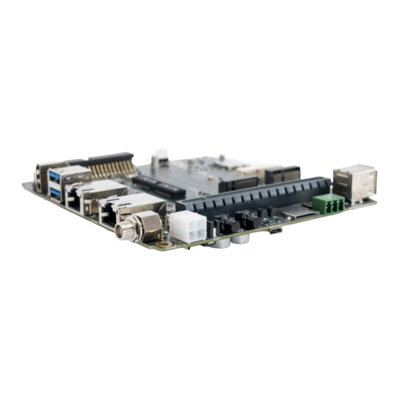
AVerMedia D315 series
®
Applies to NVIDIA
Jetson AGX Orin 32G/64G module
AVerMedia Technologies, Inc.
No. 135, Jian 1st Rd., Zhonghe Dist., New Taipei City 23585, Taiwan
Tel: 886-2-2226-3630
Fax: 886-2-3234-4842
Sales and Marketing: Contact
Technical Support: Professional User
0
D315 User Manual
AVerMedia Technologies, Inc www.avermedia.com
Advertisement
Table of Contents

Related Manuals for Avermedia D315AOB


Summarization of Contents
Limited Product Warranty
Copyright Notice
Legal notice regarding document content and intellectual property rights.
Trademark Acknowledgement
ESD Warning
Safety precautions for handling electronic components to prevent electrostatic discharge damage.
Product Overview
Block Diagram
Visual representation of the system's components and their interconnections.
Carrier Board Interface
Top View Interface
Details connectors and features visible on the top side of the carrier board.
Bottom View Interface
Details connectors and features visible on the bottom side of the carrier board.
Feature Description
Jetson Module Connector
Provides connection for the NVIDIA Jetson AGX module.
Fan Power Connector
Details the fan power connector, including pinout and specifications.
RTC Battery Connector
Specifies the connector for the RTC battery.
HDMI Output
Describes the HDMI output connector.
USB 3.2 Gen 2 Type-A Connector #1, #2
Details the dual-port USB 3.2 Gen 2 Type-A connectors.
M.2 E Key 2230
Specifies the M.2 E key slot for expansion cards.
M.2 M Key 2280
Specifies the M.2 M key slot for storage or other cards.
USB 2.0 Micro B Connector
Details the USB 2.0 Micro B connector used for BSP installation.
Micro SD Card Slot
Describes the slot for Micro SD cards.
10 Gigabit Ethernet Connector
Details the 10 Gb Ethernet port for high-speed networking.
40-Pin Expansion Header
Lists the pins and functions of the 40-pin expansion header.
Audio Pin Header
Specifies the pinout for the audio header.
Gigabit Ethernet Connector
Details the standard Gigabit Ethernet port.
Micro SIM Card Socket
Describes the slot for Micro SIM cards.
Mini Card Socket
Specifies the Mini Card socket for PCIe interface cards.
OOB Board Connector
Details the Out-of-Band (OOB) board connectors for control.
DC Power Jack
Specifies the DC power input jack.
ATX 4P
Details the ATX 4-pin power connector.
USB 2.0 Gen 1 Type-A Connector #1, #2
Describes the dual-port USB 2.0 Gen 1 Type-A connectors.
12V Power Connector for Daughter Board
Details the 12V power connector for daughter boards.
PCIE x16 Socket
Specifies the PCIe x16 slot for expansion cards.
Board to Board Connector (to Camera Board)
Details the connector for interfacing with a camera board.
CAN Bus 3-Pin Terminal Block with Transceiver
Describes the CAN bus terminal block for communication.
Debug Port
Details the debug port for system diagnostics.
SW1 Switch Button
Details the function of the SW1 DIP switch.
Power & Recovery Button
Details the physical buttons for power and recovery.
SW6 Switch Button
Details the function selection switches for Mini Card.
Installation
BSP Setup Instructions
Guides on setting up the Board Support Package (BSP).
Software
Power Mode
Describes how to manage system power modes.
RTC Battery
Information on reading the RTC battery voltage.
Fan Speed
Commands to check and control fan speed.
Camera
GPIO Usage
Demonstrates how to use GPIO pins for input and output.
Accessory Drawings
Fan Module/ Adapter/ Power Cord
Provides technical drawings for accessory components.
Need help?
Do you have a question about the D315AOB and is the answer not in the manual?
Questions and answers