Table of Contents
Advertisement
Quick Links
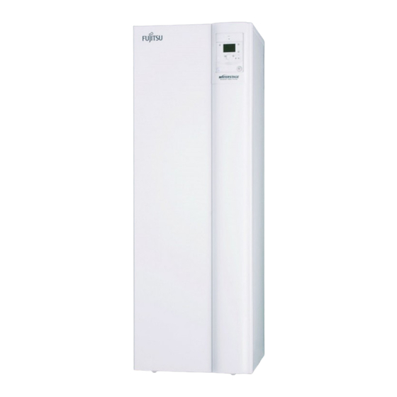
alféa extensa duo +
Heat pump air/water
split 2 services
Outdoor unit
WOYA060LDC
WOYA080LDC
WOYA100LDT
Hydraulic unit
023208
023209
Document n° 1578-4 ~ 12/12/2013
FR
NL
DE
EN
ES
PT
PL
PT
Installation and
operating manual
intended for professionals
To be saved for
future consultation
atlantic-comfort.com
Subject to modifications without notice.
Non contractual document.
IT
PT
Advertisement
Table of Contents

Summarization of Contents
1 Description of the unit
1.1 Package
Lists items included in the heat pump package, detailing outdoor unit and hydraulic unit contents.
1.2 Definitions
Explains key technical terms used in the manual, such as Split, Air/water, Inverter, and COP.
2 Installation
2.1 Regulation installation and maintenance conditions
Specifies regulatory requirements and conditions for professional installation and maintenance.
2.2 Unpacking and reservations
Details procedures for receiving, inspecting, and handling the unit to prevent transport damage.
2.3 Installation position
Provides guidance on selecting an optimal installation site for the outdoor and hydraulic units.
2.4 Installation of the outdoor unit
Outlines precautions and minimum clearance requirements for installing the outdoor unit.
2.5 Installing the hydraulic unit
Covers installation precautions and space requirements for the indoor hydraulic unit.
2.6 Refrigeration connections
Details rules, tools, and techniques for creating and connecting refrigeration pipes safely.
2.7 Filling the installation with gas
Explains the process of vacuuming and filling the refrigerant circuit, including essential safety measures.
2.8 Hydraulic connecting
2.8.1 General
Covers general practices for hydraulic connections, including pipe sizing and sealing.
2.8.2 Connecting to the DHW circuit
Explains how to connect domestic hot water pipes and the DHW sensor.
2.8.3 Rinsing out the installation
Describes the process of rinsing the heating system to remove impurities before connection.
2.8.4 Filling and purging the installation
Guides on filling the hydraulic circuit with water and removing air.
2.8.5 Connecting the Fan convector or dynamic radiator circuit
Details connecting fan convectors/radiators and buffer tank requirements.
2.11 Electrical connections
2.11.1 Characteristic of the electrical supply
Details required electrical supply characteristics, voltage, frequency, and protection.
2.11.2 General remarks on electrical connections
Provides general advice on making electrical connections, including wire types and terminals.
2.11.3 Overview of all the electrical connections
Presents a diagram showing all electrical connections for a typical installation.
2.11.4 Cable section and protection rating
Specifies cable sizes and circuit breaker ratings for power and interconnections.
2.11.5 Electrical connections on the outdoor unit side
Explains how to access and make electrical connections on the outdoor unit.
2.11.6 Electrical connections on the hydraulic unit side
Details electrical connections on the hydraulic unit, including options and external controls.
2.13 Room thermostat and/or room control unit
2.13.1 Installing a room sensor
Provides instructions for installing and connecting room thermostats (T37, T55).
2.13.2 Installing a room control unit
Guides on installing and connecting room control units (T75, T78).
2.13.3 Fan convectors or dynamic radiators area
Advises against using room sensors in specific installation areas like fan convector zones.
3 Regulation system
3.1 User interface, Room control unit (option) and Room thermostat (option)
Describes the user interface, room control unit, and room thermostat for system operation and settings.
3.3 Temperature control
3.3.1 Set to
Explains how to parameter temperature control curves based on emitter type and dwelling insulation.
3.4 Parametering the setting
3.4.1 General
Details the levels of access (User, Commissioning, Engineer) for parameter adjustments.
3.4.2 Setting parameters
Outlines the procedure for navigating menus and adjusting system parameters.
3.4.3 Recommended settings according to the heat emitters installation
Provides suggested settings for heating curve slope and flow temperature based on emitter types.
4 Overall hydraulic layout
• Configuration 1: 1 heating circuit
Illustrates the hydraulic layout for a single heating circuit system, showing component connections.
• Configuration 2: 2 heating circuits
Illustrates the hydraulic layout for a dual heating circuit system, showing component connections.
6 Troubleshooting
6.1 Faults displayed on the hydraulic unit
Lists error codes and descriptions for faults indicated on the hydraulic unit's display.
7 Maintenance of the installation
7.1 Hydraulic checks
Details annual checks for the hydraulic circuit, including pressure, safety valves, and distribution valve.
7.2 Maintenance of the DHW tank
Explains yearly maintenance for the DHW tank, including emptying and descaling procedures.
7.3 Checking the outdoor unit
Describes maintenance for the outdoor unit, focusing on heat exchanger cleaning and airflow.
7.4 Electrical checks
Covers inspections of electrical connections, cables, and indicator lights for proper function.
8 Maintenance
8.1 Emptying the hydraulic unit
Provides step-by-step instructions for emptying the hydraulic unit.
8.2 Distribution valve
Explains the correct orientation and fitting procedure for the distribution valve.
8.3 ACI check
Details how to perform checks on the ACI system, including polarity and voltage.
10 Quick-start procedure
10.1 Start-up check-list
Lists essential checks before initial start-up, covering sight, hydraulic, refrigeration, and electrical aspects.
10.1.2 Starting-up
Guides the user through the initial startup sequence, including preheating and system checks.
10.2 Settings sheet
Provides a summary table of all configurable settings for the heat pump system.
10.3 Start-up data sheet
A form for recording critical data during the heat pump's initial start-up and installation.


Need help?
Do you have a question about the WOYA060LDC and is the answer not in the manual?
Questions and answers