
Related Manuals for CLIVET WSAN-XEM 80.4


Summarization of Contents
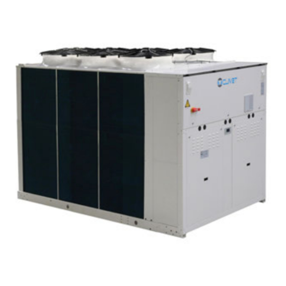
General description
Manual
The manual provides correct unit installation, use and maintenance.
Preliminaries
Only qualified personnel can operate on the unit, as required by the regulation in force.
Risk situations
The unit has been designed and created to prevent injures to people.
Intended use
Use the unit only: for cooling/heating water or a water and glycol mix for air-conditioning only.
Installation
The positioning, hydraulic system, refrigerating, electrics and the ducting of the air must be determined by the system designer.
Maintenance
Plan periodic inspection and maintenance in order to avoid or reduce repairing costs.
Modification
All unit modifications will end the warranty coverage and the manufacturer responsibility.
Breakdown/Malfuction
Disable the unit immediately in case of breakdown or malfunction.
User training
The installer has to train the user on: Start-up/shutdown, Set points change, Standby mode, Maintenance.
Data update
Continual product improvements may imply manual data changes.
Indications for the User
Keep this manual with the wiring diagram in an accessible place for the operator.
Unit indentification
The serial number label is positioned on the unit and allows to indentify all the unit features.
Serial number
It identifies uniquely each unit.
Assistance request
Note data from the serial number label and write them in the chart on side, so you will find them easily when needed.
Reception
Storage
Observe external packaging instructions.
Handling
Verify unit weight and handling equipment lifting capacity.
Packaging removing
Be careful not to damage the unit.
Anti-vibration mount support
Option
Positioning
Functional spaces
Functional spaces are designed to: guarantee good unit operation, carry out maintenance operations, protect authorized operators.
Positioning
Units are designed to be installed: EXTERNAL, in fixed positions.
Condensate water
When a heat pump is running it produces a considerable amount of water due to the defrosting cycles of the external coil.
Saftey valve gas side
The installer is responsible for evaluating the opportunity of installing drain tubes, in conformity with the local regulations.
Water connections
Water quality
Water features: confirming to local regulations, total hardness < 14°fr, within the limits indicated by table.
Risk of freezing
If the unit or the relative water connections are subject to temperatures close to 0°C.
Anti-freeze solution
The use of an anti-freeze solution results in an increase in pressure drop.
Water flow-rate
The project water-flow must be: inside the exchanger operating limits.
Minimum system water content
Minimum system water volumes are described within 'General technical data' section.
Hydraulic connections
take away the supplied connection union by acting on the connection joint, weld the union to the installation pipe.
Recommended connection
The installer must define: component type, position in system.
Water filter
Use filter with mesh pitch: 1,6 mm.
Flow Switch
The flow switch must be present to ensure shutdown of the unit if water is not circulating.
Operation sequence
Close all vent valves in the high points of the unit hydraulic circuit.
Domestic Hot Water Valve
Option
Partial energy recovery
A configuration which enables the production of hot water free-of-charge while operating in the cooling mode.
Electrical connections
Electrical date
The serial number label reports the unit specific electrical data, included any electrical accessories.
Connections
Refer to the unit electrical diagram (the number of the diagram is shown on the serial number label).
Signals / data lines
Do not exceed the maximum power allowed, which varies, according to the type of signal.
Power input
Fix the cables: if vacated may be subject to tearing.
Connections perfomer by customer
List of terminal connections and their functions.
Computer connection
Service keypad, RJ45: standard connection, P.C.-not supplied, P.C. connection.
Modbus - RS485
Option
LonWorks
Option
BACnet IP
Option
Remote control
Option
Start-up
General description
The indicated operations should be done by qualified technician with specific training on the product.
Preliminary checks
For details refer to the different manual sections.
Start-up sequence
For details refer to the different manual sections.
Refrigeration circuit
Check carefully the refrigerating circuit: the presence of oil stains can mean leakage caused by transportation, movements or other).
Water circuit
Before realizing the unit connection make sure that the hydraulic system has been cleaned up and the cleaning water has been drained.
Electric Circuit
Verify that the unit is connected to the ground plant.
Compressor crankcase heaters
Connect the oil resistances on the compressor crankcase at least 8 hours before the compressor is to be starter.
Voltages
Check that the air and water temperatures are within in the operating limits.
Remote controls
Check that the remote controls (ON-OFF etc) are connected and, if necessary, enabled with the respective parameters.
Demand limit
Menu accessible only after having entered the password.
Climatic TExt
Menu accessible only after having entered the password.
Water reset
Menu accessible only after having entered the password.
ECOSHARE function for the automatic management of a group of units
Max 7 units, Maximum length of the bus line: 700 m.
MODE A
Every unit manages its own compressors according to the setpoint.
MODE B
The master manages the single cooling.
MODE C
The master manages the single cooling.
Evaporator water flow-rate
Check that the difference between the temperature of exchanger return and supply water corresponds to power.
Start-up report
Identifying the operating objective conditions is useful to control the unit over time.
Operating at reduced load
The units are equipped with partialization steps and they can, therefore, operate with reduced loads.
2014/68/UE PED directive
DIRECTIVE 2014/68/UE PED gives instructions for installers, users and maintenance technicians as well.
Control
Led
INFO, ALARM, CANCEL
Display
Variables like Date, Time, ActualSetPoint, T.InH20UtilitySide, T.OutH20UtilitySide, ActualState, ActualMode.
Keys
Symbol, Name, Description for Info, Alarm, Cancel, Up, Down, Enter.
Change unit state
Step Display, Action, Menu/Variable, Keys, Notes.
Change the mode
Step Display, Action, Menu/Variable, Keys, Notes.
Modify setpoint
Step Display, Action, Menu/Variable, Keys, Notes.
Scheduler
It is possible to set 6 events (Off, Eco, On, Recirculating) for each week day.
Display the status
Step Display, Action, Menu/Variable, Keys, Notes.
Keyboard settings
Step Display, Action, Menu/Variable, Keys, Notes.
Alarms
Before resetting an alarm identify and remove its cause.
General list of alarms
ELECTRICAL CIRCUIT ALARMS
Maintenance
General description
Maintenance must be done by authorized centres or by qualified personnel.
Inspections frequency
Perform an inspection every 6 months minimum.
Unit booklet
It's advisable to create a unit booklet to take notes of the unit interventions.
Standby mode
If a long period of inactivity is foreseen: turn off the power, avoid the risk of frost.
Air coil
Contact with the exchanger fins can cause cuts: wear protective gloves to perform the above described operations.
Electric fans
Check: the fans and the relative protection grids are well fixed.
Water side exchanger
It is very important for the exchanger to be able to provide the maximum thermal exchange.
Circulating pumps
Check: no leaks, bearing status (anomalies are highlighted by abnormal noise and vibration).
Water filter
Check that no impurities prevent the correct passage of water.
Flow Switch
controls the operations, remove incrustations from the palette.
Compressor supply line shut-off valve
Do not remove the seal, Remove only if authorized by the manufacturer.
Crankcase heater
Check: closure, Operation.
Copeland scroll compressor
Advanced Scroll Temperature Protection
Insulations
Check the condition of the insulations: if necessary apply glue and and renew the seals.
System discharge
1. evacuate the system, 2. open all drain valves in the low points of the unit hydraulic circuit.
Accessories
VARYFLOW + (2 inverter pumps)
Water diagram
Hydronic assembly with 1 ON/OFF pump
Water diagram
Hydronic assembly with 2 ON/OFF pumps
Water diagram
Anti-vibration mount support
PE code, Type: C...., Type: R....
Decommissioning
Disconnecting
Only authorised personnel must disconnect the unit. Avoid leak or spills into the environment.
Dismantling and disposal
The unit must always be sent to authorised centres for dismantling and disposal.
Directive EC RAEE
The manufacturer is registered on the EEE National Register, in compliance with implementation of Directive 2012/19/EU.
Residual risks
General description
In this section the most common situations are indicated, as these cannot be controlled by the manufacturer.
Handling
The handling operations, if implemented without all of the protection necesssary and without due caution, may cause the drop or the tipping of the unit.
Installation
The incorrect installation of the unit could cause water leaks, condensate accumulation, leaking of the refrigerant, electric shock.
General risks
Smell of burning, smoke or other signals of serious anomalies may indicate a situation which could cause damage to people, things or the unit itself.
Electric parts
An incomplete attachment line to the electric network or with incorrectly sized cables and/or unsuitable protective devices can cause electric shocks.
Moving parts
Contact with the transmissions or with the fan aspiration can cause injuries.
Refrigerant
The intervention of the safety valve and the consequent expulsion of the gas refrigerant may cause injuries and intoxication.
Hydraulic parts
Defects in tubing, the attachments or the removal parts may cause a leak or water projection.
Dimensional
Size 50.4-55.4 - 60.4 - 65.4
Table of dimensions for models 50.4 to 65.4.
Size 70.4-80.4 -90.4
Table of dimensions for models 70.4 to 90.4.
Size 100.4-110.4 -120.4
Table of dimensions for models 100.4 to 120.4.
Need help?
Do you have a question about the WSAN-XEM 80.4 and is the answer not in the manual?
Questions and answers