
Related Manuals for CLIVET SPHERA EVO 2.0


Summary of Contents for CLIVET SPHERA EVO 2.0
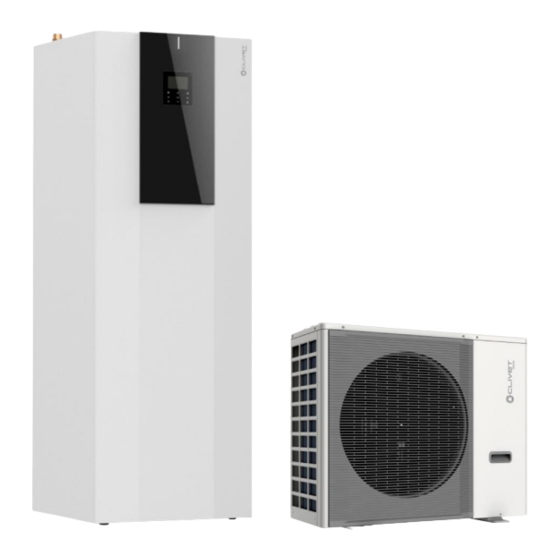
- Page 1 Service Manual SPHERA EVO 2.0 SQKN-YEE 1 TC+MiSAN-YEE 1 S 2.1-8.1 SM21G011GB-00 27-03-2023...
- Page 3 CONTENTS Part 1 General Information ..................4 Part 2 Component Layout and Refrigerant Circuits ............6 Part 3 Control ......................15 Part 4 Diagnosis and Troubleshooting ................ 29 Part 1 General Information 1 External Appearance ....................... 4...
- Page 4 1 External Appearance 1.1 Outdoor Unit Appearance Table 1-1.1: Outdoor unit appearance MiSAN-YEE 1 S 2.1 - 3.1 MiSAN-YEE 1 S 4.1 - 8.1 1.2 Indoor Unit Table 1-1.2: Indoor unit appearance SQKN-YEE 1 TC 190L SQKN-YEE 1 TC 250L Outdoor unit Size 2.1-3.1...
- Page 6 Part 2 Component Layout and Refrigerant Circuits 1 Layout of Functional Components .................. 7 2 Piping Diagrams ......................12 3 Refrigerant Flow Diagrams .................... 14...
- Page 7 1 Layout of Functional Components 1.1 Outdoor Unit Layout MiSAN-YEE 2.1 - 3.1 (single-phase) Figure 2-1.1: top view Air side heat exchanger Pressure sensor HP pressure switch Separator LP pressure switch Electric control box Figure 2-1.2: front view 4-way valve Gas side stop valve Liquid side stop valve DC inverter compressor...
- Page 8 MiSAN-YEE 4.1 - 5.1 (single-phase) Figure 2-1.3: top view Air side heat exchanger HP pressure switch Pressure sensor LP pressure switch Figure 2-1.4: front view Electric control box 4-way valve Gas side stop valve Liquid side stop valve DC inverter compressor Separator...
- Page 9 MiSAN-YEE 6.1 - 8.1 (single-phase) Figure 2-1.5: top view Air side heat exchanger HP pressure switch Pressure sensor Pressure sensor 4-way valve LP pressure switch Figure 2-1.6: front view Electric control box Liquid side stop valve Gas side stop valve DC inverter compressor...
- Page 10 MiSAN-YEE 6.1 - 8.1 (three-phase) Figure 2-1.7: top view Air side heat exchanger HP pressure switch Pressure sensor Separator 4-way valve LP pressure switch Figure 2-1.8: front view Electric control box Liquid side stop valve Gas side stop valve DC inverter compressor...
- Page 11 1.2 Indoor Unit Layout heat exchanger system circulator magnesium anode system pressure relief valve (3bar) flow switch magnetic dirt separator filter 8L expansion tank (system side) Electric control box 3-way valve connections to the solar system Storage tank probe 190-250L DHW storage tank discharge 2kW heater...
- Page 12 2 Refrigeration Circuit Diagram 2.1 Outdoor Unit Piping Figure 2-2.1: water diagram Indoor unit Air side heat exchanger Compressor Stop valve (liquid side) Compressor discharge pipe temperature sensor Stop valve (gas side) Outdoor ambient temperature sensor Pressure sensor Air side heat exchanger refrigerant outlet temperature sensor Separator Compressor suction pipe temperature sensor LP pressure switch...
- Page 13 2.2 Water Circuit Diagram SQKN-YEE 1 TC - 190 L/250 L Figure 2-2.2: water diagram...
- Page 14 3 Refrigerant Flow Diagrams Heating and domestic hot water operation Figure 2-3.1: refrigerant flow during heating or domestic hot water operation High temperature, high pressure gas High temperature, high pressure liquid Low temperature, low pressure Indoor unit Pressure sensor Stop valve 4-way Air side heat valve...
-
Page 15: Table Of Contents
Part 3 Control 1 Stop Operation ......................16 2 Standby Control ......................16 3 Startup Control ......................17 4 Normal Operation Control .................... 20 5 Protection Control ......................22 6 Special Control ......................25 7 Role of Temperature Sensors in Control Functions ............27... -
Page 16: Stop Operation
1 Stop Operation The stop operation occurs for one of the following reasons: 1. Abnormal shutdown: in order to protect the compressors, if an abnormal state occurs the system makes a stop with thermo off operation and an error code is displayed on the outdoor unit PCB digital displays and on the user interface. 2. -
Page 17: Startup Control
The compressor re-start delays for cooling and heating modes are set on the user interface. Refer to the Installation manual of Sphera EVO 2.0 > chapter 9 Heating/Cooling mode setting. 3.2 Compressor Startup Program In initial startup control and in re-start control, compressor startup is controlled according to outdoor ambient temperature. - Page 18 Figure 3-3.3: MiSAN-YEE 1 S 4.1 - 5.1 single-phase compressor startup program1 when ambient temperature is above 11°C Compressor rotation speed (rps) Target rotation speed Time Notes: Once the first, 90-second stage of the program is complete, the program proceeds to the subsequent stages in a step-by-step fashion and exits when the target rotation speed has been reached.
- Page 19 Figure 3-3.6: MiSAN-YEE 1 S 6.1 - 8.1 single-phase / three-phase 1 compressor1 startup program when ambient temperature is at or below 3°C Compressor rotation speed (rps) Target rotation speed Time Notes: Once the first, 40-second stage of the program is complete, the program proceeds to the subsequent stages in a step-by-step fashion and exits when the target rotation speed has been reached.
-
Page 20: Normal Operation Control
3.3 Startup Control for Heating and Domestic Hot Water Operation Table 3-3.1: Component control during startup in heating and domestic hot water modes Wiring diagram Component 4-16kW Control functions and states label Compressor startup program selected according to ambient DC inverter compressor COMP •... - Page 21 Table 3-4.2: Component control during cooling operation Wiring diagram Component 4-16kW Control functions and states label Controlled according to load requirement from hydronic DC inverter compressor COMP • system Controlled according to outdoor heat exchanger pipe • temperature Position (steps) from 0 (fully closed) to 480 (fully open), controlled according to outdoor ambient temperature, Electronic expansion valve •...
-
Page 22: Protection Control
4.6 Outdoor Fan Control The speed of the outdoor unit fan is adjusted as shown in Table 3-4.1. Table 3-4.1: Component control during operation Fan speed (rpm) Fan speed index 4/6/8/10kW 12/14kW 10kW 5 Protection Control 5.1 High Pressure Protection Control This control protects the refrigerant circuit from abnormally high pressure and protects the compressor from transient spikes in pressure. - Page 23 When the suction pressure drops below 0.14 MPa the system displays P0 protection and the unit stops running. When the suction pressure rises above 0.3 MPa, the compressor enters re-start control. 5.3 Discharge Temperature Protection Control This control protects the compressor from abnormally high temperatures and transient spikes in temperature. Figure 3-5.3: High discharge temperature protection control Normal operation Discharge temperature >...
- Page 24 5.5 Voltage Protection Control This control protects the unit from abnormally high or abnormally low voltages. Figure 3-5.6: Compressor voltage protection control Normal operation For single-phase unit: voltage < 256 For single-phase unit: voltage ≥ 265 V for 30s or voltage ≥ 180 V V for 30s or voltage ≤...
-
Page 25: Special Control
6 Special Control 6.1 Oil Return Operation In order to prevent the compressor from running out of oil, the oil return operation is conducted to recover oil that has flowed out of the compressor and into the refrigerant piping. The oil return operation starts when the following condition occurs: ■... - Page 26 Fast DHW operation is used to quickly fulfil a requirement for domestic hot water when DHW priority has been set on the user interface. Refer to installation manual of SPHERA EVO 2.0, Part 10 “Control”. Table 3-6.5: Component control during fast DHW operation...
-
Page 27: Role Of Temperature Sensors In Control Functions
Table 3-7.1: Names of the temperature sensors Number Sensor name Sensor code Suction pipe temperature sensor Discharge pipe temperature sensor Outdoor ambient temperature sensor Air side heat exchanger refrigerant outlet temperature sensor Water side heat exchanger refrigerant outlet (gas pipe) temperature sensor Water side heat exchanger refrigerant outlet (liquid pipe) temperature sensor... - Page 29 Part 4 Diagnosis and Troubleshooting 1 Electric Control Box Layout ................... 30 2 PCBs ..........................33 3 Error Code Table ......................47 4 Troubleshooting ......................49 5 Temperature Sensor Resistance Characteristics ............106 6 Control keypad ......................109...
-
Page 30: Electric Control Box Layout
1 Electric Control Box Layout 1.1 Outdoor Unit Electric Control Box Layout Figura 4-1.1: MiSAN-YEE 1 S 2.1 – 3.1 (single-phase) electric control box Main PCB Inverter module MiSAN-YEE 1 S 4.1 – 5.1 (single-phase) electric control box Main PCB Inverter module... - Page 31 MiSAN-YEE 1 S 6.1 – 8.1 (single-phase) electric control box Main PCB Inverter module MiSAN-YEE 1 S 6.1 – 8.1 (three-phase) electric control box Main PCB Inverter module Transformer Filter board DC fan transformer...
- Page 32 1.2 Indoor Unit Electric Control Box Layout Figure 4-1.2: Indoor unit electric control box Main PCB Power supply terminals Communication terminal blocks...
-
Page 33: Pcbs
2 PCBs 2.1 Outdoor Unit PCBs The main PCB is the same for all 4kW to 16kW models. In addition, all models have an inverter module. The locations of each PCB in the outdoor unit electric control box are shown in Figures 4-1.1 in Part 4, 1.1 ”Outdoor Unit Electric Control Box Layout”. - Page 34 Table 4-2.1: Indoor unit main PCB Label in Code Description Figure 4-2.1 CN21 Port for power supply Rotary Dip switch DSI1 Digital display Port for GND CN28 Port for variable speed pump power input CN25 Port for IC programming S1,S2,S4 Dip switch Port for USB programming Port for flow switch...
- Page 35 2.3 Main PCBs for Inverter Module Figure 4-2.2: MiSAN-YEE 1 S 2.1 - 5.1 single-phase outdoor unit 1ph main PCB for refrigerant system1 Notes: Label descriptions are given in Table 4-2.2.
- Page 36 Table 4-2.2: MiSAN-YEE 1 S 2.1 - 5.1 single-phase outdoor unit main PCB for refrigerant system Label in Code Description Figure 4-2.2 CN28 Output port L to main PCB for refrigerant system CN22 Reserved CN27 Output port N to main PCB for refrigerant system Reserved Port for ground wire DSP1...
- Page 37 Figure 4-2.3: MiSAN-YEE 1 S 6.1 - 8.1 single-phase outdoor unit 1ph main PCB for refrigerant system1 Notes: Label descriptions are given in Table 4-2.3.
- Page 38 Table 4-2.3: MiSAN-YEE 1 S 6.1 - 8.1 single-phase outdoor unit main PCB for refrigerant system Label in Code Description Figure 4-2.3 CN28 Output port L to main PCB for refrigerant system CN22 Reserved CN27 Output port N to main PCB for refrigerant system Reserved Port for ground wire DSP1...
- Page 39 Figure 4-2.4: MiSAN-YEE 1 S 6.1 - 8.1 three-phase outdoor unit 3ph main PCB for refrigerant system1 Notes: Label descriptions are given in Table 4-2.4.
- Page 40 Table 4-2.4: MiSAN-YEE 1 S 6.1 - 8.1 three-phase outdoor unit main PCB for refrigerant system Label in Code Description Figure 4-2.4 CN38 Port for GND CN27 Port for 2-way valve 6 CN20 Port for 2-way valve 5 Port for electric heater 2 CN10 Port for electric heater 1 CN11...
- Page 41 Figure 4-2.5: MiSAN-YEE 1 S 2.1 -3.1 single-phase outdoor unit inverter module1 MiSAN-YEE 1 S 4.1 -5.1 single-phase Notes: Label descriptions are given in Table 4-2.5.
- Page 42 Table 4-2.5: Outdoor unit inverter module Label in Code Description Figure 4-2.5 Compressor connection port U Compressor connection port V Compressor connection port W CN20 Output port for +12V/9V CN19 Port for fan CN32 Port for communication with main PCB for filter board CN501 Input port L for rectifier bridge CN502...
- Page 43 Figure 4-2.6: MiSAN-YEE 1 S 6.1 -8.1 single-phase outdoor unit inverter module1 Notes: Label descriptions are given in Table 4-2.6. Table 4-2.6: Outdoor unit inverter module Label in Code Description Figure 4-2.6 Compressor connection port U Compressor connection port V Compressor connection port W CN19 Port for fan...
- Page 44 Figure 4-2.7: MiSAN-YEE 1 S 6.1 -8.1 three-phase outdoor unit inverter module1 Notes: Label descriptions are given in Table 4-2.7. Table 4-2.7: Outdoor unit inverter module Label in Code Description Figure 4-2.7 CN20 Output port for +15V CN19 Compressor connection port W CN18 Compressor connection port V CN17...
- Page 45 Figure 4-2.8: MiSAN-YEE 1 S 6.1-8.1 three-phase outdoor unit filter board1 Notes: Label descriptions are given in Table 4-2.8. Table 4-2.8: Outdoor unit filter board Label in Code Description Figure 4-2.8 CN201 L2 power supply CN200 L3 power supply CN203 N power supply CN212 Port for 310VDC power supply...
- Page 46 2.4 DIP switch setting and wire connecting for Modbus function The rotating coded switch S3(0-F) on the main control board of hydraulic module is used for setting the Modbus address. By default the units have this coded switch positioned=0, but this corresponds to the Modbus address 16, while the others positions corresponds the number, e.g.
-
Page 47: Error Code Table
3 Error Code Table Error Serial Content Remarks code number Transducer module temperature too high Water flow error (E8 is displayed 3 times) Applies to three-phase models Phase sequence error only Communication error between the main control board of hydraulic module and user interface Leaving water temperature sensor error T1 sensor... - Page 48 Circuit 2 water outlet temperature sensor error Tw2 sensor Water side heat exchanger water outlet temperature sensor error Tw_out sensor PP protection appears three times in succession and Twout<7℃ Inverter module EEPROM error Fan DC error (E6 is displayed 10 times in 120min) Low pressure protection in cooling mode Low pressure protection High pressure protection...
-
Page 49: Troubleshooting
4 Troubleshooting 4.1 Warning Warning All electrical work must be carried out by competent and suitably qualified, certified and accredited professionals and in accordance with all applicable legislation (all national, local and other laws, standards, codes, rules, regulations and other legislation that apply in a given situation). - Page 50 4.2 E0, E8 Troubleshooting 4.2.1 Digital display output 4.2.2 Description • Water flow error. • E0 indicates that E8 has been displayed 3 times. When E0 error occurs, a manual system restart is required before the system can resume operation. •...
- Page 51 4.2.4 Procedure E0/E8 Water flow switch connection on indoor unit Ensure the flow switch is connected properly main PCB is loose Check the water piping and valves. Make sure the water piping is clean, there is no air in the water piping and all valves are open.
- Page 52 4.3 E1 Troubleshooting 4.3.1 Digital display output 4.3.2 Description • Phase sequence error. • Applies to three-phase models only. • The unit stops running. • Error code is displayed on outdoor unit main PCB and user interface. 4.3.3 Possible causes •...
- Page 53 4.3.4 Procedure The phase sequence of the three-phase Swap any two of the 3 phase wires power supply is incorrect Ensure that all power supply terminals are Some power supply terminals are loose connected properly Check the power supply equipment Power supply is abnormal Replace the refrigerant system main board...
- Page 54 4.4 E2 Troubleshooting 4.4.1 Digital display output 4.4.2 Description • Communication error between indoor unit and user interface. • SPHERA EVO stops running. • Error code is displayed on indoor unit main PCB and user interface. 4.4.3 Possible causes • Communication wires between indoor unit and user interface not connected properly.
- Page 55 4.4.4 Procedure Reconnect the communication wires Communication wires X Y E have short-circuited, disconnected or are misconnected Communication wires X Y are not connected Connect the communication wires in a daisy chain in a daisy chain Wires between indoor unit main PCB and electric control Ensure the wires are connected properly box communication terminal block are loose Ensure that communication and high voltage wires are...
- Page 56 4.5 E3, E4, H3, Ed, HA, H5, H9, Eb, E7, Ec Troubleshooting 4.5.1 Digital display output 4.5.2 Description ■ E3 indicates a backup electric heater water outlet temperature sensor error (T1) ■ E4 indicates a domestic hot water tank temperature sensor error (T5) ■...
- Page 57 4.5.4 Procedure E3/E4/H3/Ed/HA/H5/H9/Eb/E7/Ec Temperature sensor connection on indoor unit Ensure the sensor is connected properly main PCB is loose Temperature sensor has short-circuited or failed Replace the sensor Replace indoor unit main PCB Notes: End water outlet temperature sensor, water side heat exchanger refrigerant inlet (liquid pipe) temperature sensor, water side heat exchanger refrigerant outlet (gas pipe) temperature sensor, water side heat exchanger water inlet temperature sensor and water side heat exchanger water outlet temperature sensor connections are port CN6 on the indoor unit main PCB (labelled 10 in Figure 4-2.1 in Part 4, 2.2 "Main Board for Hydronic System").
- Page 58 4.6 E5, E6, E9, EA Troubleshooting 4.6.1 Digital display output 4.6.2 Description ■ E5 indicates an air side heat exchanger refrigerant outlet temperature sensor error. ■ E6 indicates an outdoor ambient temperature sensor error. ■ E9 indicates a suction pipe temperature sensor error. ■...
- Page 59 4.6.4 Procedure E5/E6/E9/EA Temperature sensor connection on outdoor unit Ensure the sensor is connected properly main PCB is loose Temperature sensor has short-circuited or failed Replace the sensor Replace outdoor unit main PCB Notes: Air side heat exchanger refrigerant outlet temperature sensor and outdoor ambient temperature sensor connections are port CN9 on the outdoor unit main PCB MiSAN-YEE 1 S 2.1-5.1 single-phase (labelled 12 in Figure 4-2.2 in Part 4, 2.1 “Main PCBs for Refrigerant System, Inverter Module”), port CN9 on the outdoor unit main PCB MiSAN-YEE 1 S.
- Page 60 4.7 EE Troubleshooting 4.7.1 Digital display output 4.7.2 Description ■ Indoor unit main PCB EEPROM error. ■ The unit stops running. ■ Error code is displayed on indoor unit main PCB and user interface. 4.7.3 Possible causes ■ Indoor unit main PCB EEPROM is not connected properly. ■...
- Page 61 4.8 F1 Troubleshooting 4.8.1 Digital display output 4.8.2 Description ■ Low DC generatrix voltage. ■ The unit stops running. ■ Error code is displayed on indoor unit main PCB and user interface. 4.8.3 Possible causes ■ The DC generatrix voltage is too low 4.8.4 Procedure Power supply is abnormal.
- Page 62 4.9 HF Troubleshooting 4.9.1 Digital display output 4.9.2 Description ■ Outdoor unit main PCB EEPROM error. ■ The unit stops running. ■ Error code is displayed on outdoor unit main PCB and user interface. 4.9.3 Possible causes ■ Outdoor unit main PCB EEPROM is not connected properly. ■...
- Page 63 4.10 H0 Troubleshooting 4.10.1 Digital display output 4.10.2 Description ■ Communication error between outdoor unit and indoor unit. ■ The unit stops running. ■ Error code is displayed on indoor unit main PCB, outdoor unit main PCB and user interface. 4.10.3 Possible causes ■...
- Page 64 4.10.4 Procedure Power supply for the main control board and Provide normal power supply. transformer is abnormal The transformer of indoor unit has Replace the transformer malfunctioned There is a source of electromagnetic radiation near the unit, such as high-frequency transmitter Remove the source of interference or other high strength radiation device Communication wires P Q E between main...
- Page 65 4.11 H1 Troubleshooting 4.11.1 Digital display output 4.11.2 Description ■ Communication error between outdoor unit main control board and inverter module. ■ The unit stops running. ■ Error code is displayed on outdoor unit main PCB and user interface. 4.11.3 Possible causes ■...
- Page 66 4.12 H6, HH Troubleshooting 4.12.1 Digital display output 4.12.2 Description ■ H6 indicates a DC fan error. ■ HH indicates that H6 protection has occurred 10 times in 2 hours. When HH error occurs, a manual system restart is required before the system can resume operation. The cause of HH error should be addressed promptly in order to avoid system damage.
- Page 67 4.12.4 Procedure H6/HH Strong wind blows towards the fan, causing it to turn in Change the outdoor unit’s installation direction or build the wrong direction a shelter to protect the fan from strong wind DC fan wire is loose Reconnect DC fan wire The fan motor is blocked or has failed Remove obstruction or replace fan motor Inverter module is damaged...
- Page 68 4.13 H7 Troubleshooting 4.13.1 Digital display output 4.13.2 Description ■ Abnormal main circuit voltage. ■ The unit stops running. ■ Error code is displayed on outdoor unit main PCB and user interface. 4.13.3 Possible causes ■ Power supply voltage not within 90%~110% of rated voltage. ■...
- Page 69 4.14 H8 Troubleshooting 4.14.1 Digital display output 4.14.2 Description ■ High pressure sensor error ■ SPHERA EVO stops running. ■ Error code is displayed on outdoor unit main PCB and user interface. 4.14.3 Possible causes ■ Temperature sensor not connected properly or has malfunctioned. ■...
- Page 70 4.15 P0, HP Troubleshooting 4.15.1 Digital display output 4.15.2 Description ■ P0 indicates suction pipe low pressure protection. When the suction pressure falls below 0.14MPa, the system displays P0 protection and the unit stops running. When the pressure rises above 0.3MPa, P0 is removed and normal operation resumes.
- Page 71 4.15.4 Procedure P0/PH Insufficient refrigerant caused by Add refrigerant or inspect the system for leaks refrigerant leakage Inspect the system and fix the error. The low pressure side is blocked, caused by If the filter is blocked by ice, the piping should be crushed or bent pipe, blocked EXV, or dirty filter cleaned The air side heat exchanger heat exchange is poor...
- Page 72 4.16 P1 Troubleshooting 4.16.1 Digital display output 4.16.2 Description ■ Discharge pipe high pressure protection. When the discharge pressure rises above 4.3 MPa, the system displays P1 protection and the unit stops running. When the discharge pressure falls below 3.6 MPa, P1 is removed and normal operation resumes.
- Page 73 4.16.4 Procedure High pressure switch connection or pressure sensor connection on outdoor unit main PCB Ensure the pressure switch is connected properly is loose Pressure sensor has short-circuited or failed Replace the pressure sensor The high pressure side is blocked, caused by Inspect the system and fix the error crushed or bent pipe or blocked EXV The heat exchange is poor...
- Page 74 4.17 P3 Troubleshooting 4.17.1 Digital display output 4.17.2 Description ■ Compressor current protection. ■ When the compressor current rises above the protection value (4/6kW models 18A, 8/10kW model 19A, 12/14/16kW 1ph model 30°, 12/14/16kW 3ph model 14A ), the system displays P3 and the unit stops running. When the current returns to the normal range, P3 is removed and normal operation resumes.
- Page 75 4.17.4 Procedure The condenser heat exchange is poor Inspect the system and fix the error The high pressure side is blocked, caused by Inspect the system and fix the error crushed or bent pipe or blocked EXV Inverter module has short-circuited Replace the inverter module Compressor has malfunctioned Replace the compressor...
- Page 76 4.18 P4 Troubleshooting 4.18.1 Digital display output 4.18.2 Description ■ Discharge temperature protection ■ When the compressor discharge temperature rises above 115°C, the system displays P4 protection and SPHERA EVO stops running. When the discharge temperature falls below 90°C, P4 is removed and normal operation resumes. ■...
- Page 77 4.18.4 Procedure Discharge pipe temperature sensor Ensure the temperature sensor is connection on outdoor unit main PCB connected properly is loose Backup electric heat exchanger water outlet temperature sensor connection, domestic hot water tank temperature Ensure the temperature sensor is sensor connection or water side heat connected properly exchanger water outlet temperature...
- Page 78 Notes: Discharge pipe temperature sensor connection is port CN8 on the outdoor unit refrigerant system main PCB single-phase MiSAN-YEE 1 S 2.1-5.1 (labelled 15 in Figure 4-2.2 in Part 4, 2.3 “Main PCBs for Refrigerant System, Inverter Module”), port CN8 on the outdoor unit refrigerant system main PCB single- phase MiSAN-YEE 1 S.
- Page 79 4.19 P5 Troubleshooting 4.19.1 Digital display output 4.19.2 Description ■ High temperature difference between water side heater exchanger water inlet and water outlet temperatures protection. ■ The unit stops running. ■ Error code is displayed on outdoor unit main PCB and user interface. 4.19.3 Possible causes ■...
- Page 80 4.19.4 Procedure Ensure the temperature sensor is connected Water side heat exchanger water properly inlet/outlet temperature sensor is loose Water side heat exchanger water Replace the temperature sensor inlet/outlet temperature sensor has short- circuited or failed Water piping contains air Purge air from the water system The water flow rate is not sufficient, caused by crushed or bent water piping, incorrect...
- Page 81 4.20 P6 Troubleshooting for single-phase models 4.20.1 Digital display output 4.20.2 Description ■ Inverter module protection ■ The unit stops running. ■ Specific error code L0, L1, L2, L4, L5, L7, L8 or L9 is displayed on outdoor unit main PCB and user interface. 4.20.3 Possible causes ■...
- Page 82 The specific error codes can also be obtained from the LED indicators on the inverter module. Table 4-4.2: Errors indicated on LED, MiSAN-YEE 1 S 2.1-5.1 single-phase LED301 flashing pattern (green) Corresponding error LED302 always on (red) Flashes 8 times and stops for 1 second, then repeats. L0 - Inverter module protection Flashes 9 times and stops for 1 second, then repeats.
- Page 83 4.20.5 Principle of DC inverter Inductor Power Comp Bridge Inverter Contactor supply Capacitor ressor module rectifier ①. Contactor is open, the current across the PTC to charge capacitor, after 5 seconds the contactor closed. ② 220/240V AC power supply change to DC power supply after bridge rectifier. ③...
- Page 84 Situation 2: L0 or L4 error appears immediately after the compressor starts up L0 / L4 U V W wire between inverter module and Ensure U V W wire is connected properly compressor is not connected properly Replace the inverter module Inverter module is damaged Compressor has malfunctioned Replace the compressor...
- Page 85 Situation 3: L0 or L4 error appears after the compressor has been running for a period of time and the compressor speed is over 60 rps L0 / L4 Repaint the thermally conductive silica gel on the module, IGBT, diode, bridge Inverter module has overheated rectifier (on the reverse side of the inverter module PCB)
- Page 86 4.20.7 L1/L2 Troubleshooting The normal DC voltage between terminals P and N on the inverter module is 1.4 times the AC power supply in standby and 377 V when the fan motor is running. If the voltage is lower than 160V, the unit displays an L1 error. If the voltage is higher than 500V, the unit displays an L2 error.
- Page 87 Situation 2: L1 or L2 error appears after the compressor has been running for a period of time and the compressor speed is over 20 rps L1 /L2 Relay on outdoor unit main PCB is open Replace outdoor unit main PCB Replace the inverter module relay Notes:...
- Page 88 4.21 P6 Troubleshooting for three-phase models 4.21.1 Digital display output 4.21.2 Description ■ Inverter module protection ■ The unit stops running. ■ Specific error code L0, L1, L2, L4, L5, L7, L8 or L9 is displayed on outdoor unit main PCB and user interface. 4.21.3 Possible causes ■...
- Page 89 The specific error codes can also be obtained from the LED indicators LED1/LED2 on the inverter module. Table 4-4.5: Errors indicated on LEDs, MiSAN-YEE 1 S 6.1-8.1 three-phase LED1/LED2 flashing pattern Corresponding error Flashes 8 times and stops for 1 second, then repeats. L0 - Inverter module protection Flashes 9 times and stops for 1 second, then repeats.
- Page 90 4.21.6 L0 Troubleshooting Situation 1: L0 error appears immediately after the outdoor unit is switched-on Communication wire between the main Ensure the communication wire is control board of the refrigerant system for connected properly the inverter module (4-pin) is not connected properly Inverter module is damaged The voltage between pins F0 and GND of...
- Page 91 Situation 2: L0 error appears immediately after the compressor starts up Ensure the wire is connected properly DC bus wire is connected properly Compressor has malfunctioned Replace the compressor Replace outdoor unit main PCB Notes: The DC bus wire must run from terminal N on the inverter module, through the current sensor (indicated by the arrow on the current sensor) and end at terminal N on the capacitor.
- Page 92 Situation 3: L0 error appears within 2 seconds of compressor start-up U V W wire between inverter module and Ensure U V W wire is connected properly compressor is not connected properly The communication port for connection to Replace main PCB the inverter module on the refrigerant system main PCB is damaged Replace the inverter module...
- Page 93 Situation 4: L0 error appears after the compressor has been running for a period of time and the compressor speed is over 60 rps Repaint the thermally conductive silica gel on the PFC and IPM module, diode (on the Inverter module has overheated reverse side of the inverter module PCB) Inverter module is over-current Replace the compressor...
- Page 94 4.21.7 L1/L2 Troubleshooting The normal DC voltage between terminals P and N on the inverter module is 540V. If the voltage is lower than 300V, the unit displays an L1 error. If the voltage is higher than 830V, the unit displays an L2 error. Refer to Figure 4-4.9. Figure 4-4.9: Voltage terminals P,N Situation 1: L1 or L2 error appears immediately after the outdoor unit is switched-on L1/L2...
- Page 95 ; ( ) Figure 4-4.10: P N +15V Terminal -+15V IC4/5/6PIN12 IC/4/5,6 PIN13 Check the +15V circuit according to the corresponding wiring diagram. If the output power supply of the inverter module in IC4/5/6PIN12 is not +15V, the inverter module is faulty. If the output power supply of the inverter module is +15V, the main PCB is faulty. Check the bridge rectifier using one of the two following methods (refer to Figure 4-4.11) ■...
- Page 96 4.21.8 L4 Troubleshooting Situation 1: L4 error appears immediately after the outdoor unit is switched-on Replace main PCB Situation 2: L4 error appears after the compressor has been running for a period of time and the compressor speed is over 60 rps Compressor is over-current Replace the compressor Replace main PCB...
- Page 97 4.22 Pd Troubleshooting 4.22.1 Digital display output 4.22.2 Description ■ High temperature protection of air side heat exchanger refrigerant outlet in cooling mode. When the air side heat exchanger refrigerant outlet temperature is higher than 61°C for more than 3 seconds, the system displays Pd protection and the unit stops running.
- Page 98 4.22.4 Procedure Air side heat exchanger refrigerant outlet Ensure the temperature sensor is temperature sensor is loose connected properly Air side heat exchanger refrigerant outlet temperature sensor has short-circuited or Replace the temperature sensor failed The air side heat exchanger heat exchange Inspect the system and fix the error is poor The fan or fan motor is blocked or damaged...
- Page 99 4.23 PP Troubleshooting 4.23.1 Digital display output 4.23.2 Description ■ Water side heat exchanger inlet temperature is higher than outlet temperature in heating mode. ■ The unit stops running. ■ Error code is displayed on indoor unit main PCB and user interface. ■...
- Page 100 4.23.4 Procedure Water side heat exchanger water Ensure the temperature sensor is inlet/outlet temperature sensor is loose connected properly Water side heat exchanger water inlet/outlet temperature sensor has short- Replace the temperature sensor circuited or failed 4-way valve is blocked or damaged Replace 4-way valve Replace outdoor main PCB Notes:...
- Page 101 4.24 C7 Troubleshooting 4.24.1 Digital display output 4.24.2 Description ■ Transducer module temperature too high ■ The unit stops running. ■ Error code is displayed on indoor unit main PCB and user interface. 4.24.3 Possible causes ■ The unit's power supply voltage is low. ■...
- Page 102 4.24.4 Procedure Increase the power supply voltage The unit's power supply voltage is low. to the required value. The space between the units is too narrow for the heat Increase the space between units. exchanger. The heat exchanger is dirty or its surface is obstructed. Clean the heat exchanger.
- Page 103 4.25 bH Troubleshooting 4.25.1 Digital display output 4.25.2 Description ■ PED PCB failure ■ The unit stops running. ■ Error code is displayed on indoor unit main PCB and user interface. 4.25.3 Possible causes ■ Power supply problem. ■ PED board faulty. ■...
- Page 104 4.25.4 Procedure Power supply problem. After 5 minutes of shut Increase the power supply voltage to the required down, switch on again and check whether the value. problem can be solved. Replace the PED PCB and switch on again. PED board faulty.
- Page 105 4.26 Pb Troubleshooting 4.26.1 Digital display output 4.26.2 Description ■ Water side heat exchanger anti-freeze protection. ■ The unit stops running. ■ Error code is displayed on indoor unit main PCB and ANTI.FREEZE icon is displayed on user interface. 4.26.3 Possible causes ■...
-
Page 106: Temperature Sensor Resistance Characteristics
5 Temperature Sensor Resistance Characteristics Table 4-5.1: Outdoor ambient temperature sensor, water side heat exchanger refrigerant inlet/outlet (liquid/gas pipe) temperature sensor, air side heat exchanger refrigerant outlet temperature sensor and suction pipe temperature sensor resistance characteristics Temperature Resistance Temperature Resistance Temperature Resistance Temperature... - Page 107 Table: Compressor discharge pipe temperature sensor resistance characteristics Temperature Resistance Temperature Resistance Temperature Resistance Temperature Resistance (°C) (kΩ) (°C) (kΩ) (°C) (kΩ) (°C) (kΩ) 542.7 68.66 13.59 3.702 511.9 65.62 13.11 3.595 483.0 62.73 12.65 3.492 455.9 59.98 12.21 3.392 430.5 57.37 11.79...
- Page 108 Table 4-5.3: Water side heat exchanger water inlet/outlet temperature sensor, backup heat exchanger outlet water temperature sensor and DHW temperature sensor resistance characteristics Temperature Resistance Temperature Resistance Temperature Resistance Temperature Resistance (°C) (kΩ) (°C) (kΩ) (°C) (kΩ) (°C) (kΩ) 867.29 98.227 17.600 4.4381...
-
Page 109: Control Keypad
6 Control keypad Keys Function MENU To open the various menus from the HOME screen. Turn on/off heating and cooling modes or mode Turn on/off functions in the menu structure ON / OFF UNLOCK (press for 3 sec.) Unlock/lockthe keypad Enter a sub-menu Confirm the values entered LEFT - RIGHT... - Page 110 FOR SERVICEMAN FOR SERVICEMAN FOR SERVICEMAN 3/3 13. AUTO RESTART OTHER HEATING SOURCE DHW MODE SETTING HOLIDAY AWAY SETT. 14. POWER INPUT LIMIT COOL MODE SETTING SERVICE CALL 15. INPUT DEFINITION 16. CASC. SETT. 17. HMI ADDRESS SET SPECIAL FUNCTION ENTER...
- Page 112 Via Camp Lonc 25, Z.I. Villapaiera 32032 Feltre (BL) - Italy Tel. +39 0439 3131 - Fax +39 0439 313300 info@clivet.it...
Need help?
Do you have a question about the SPHERA EVO 2.0 and is the answer not in the manual?
Questions and answers