
Related Manuals for CLIVET SPHERA EVO 2.0 Box


Summary of Contents for CLIVET SPHERA EVO 2.0 Box
- Page 1 Indoor unit SPHERA EVO 2.0 - Box SQKN-YEE 1 BC 2.1-8.1 M0GM00002-07 INST 05-2024 ROMANIAN SLOVENIAN HRVATSKI BULGARIAN Keep this manual together with the wiring diagram in an accessible place for the operator for future reference.
- Page 2 Dear Customer, We congratulate you on choosing these product. Clivet has been working for years to offer systems able to assure the maximum comfort for a long time with highly-reliable, efficient, high-quality and safe solutions. The target of the company is to offer advanced systems, that assure the best comfort and reduce energy consumption as well as the installation and maintenance costs for the entire life-cycle of the system.
-
Page 3: Table Of Contents
Summary Glossary........................6 General ........................7 About the manual ...................7 General safety warnings ................8 About R-32 refrigerant ..................... 9 Warnings for the installer and the Technical Support Service ....10 General warnings ...................10 Safety checks and procedures ..............10 Installation requirements ................13 Presentation of the product .................. - Page 4 7.14 Relief valves .....................29 7.15 Loading the plant....................29 Refrigerant connections ..................31 Prerequisites ....................31 Electrical connections ....................33 Prerequisites ....................33 General diagram .....................34 Cable inlet ......................35 Connecting the power supply ...............35 External component connections ..............37 Backup heater (FE boiler) ................41 Zone thermostat .....................42 SMART GRID - Photovoltaic management ...........43 9.10...
- Page 5 14.3 Handling ......................57 14.4 Installation .......................57 14.5 Refrigerant .......................58 14.6 Hydraulic parts ....................58 Advanced applications ..................... 59 15.1 Units connected in cascade ................59 Technical data ......................63 Energy labels ......................71...
-
Page 6: Glossary
1. Glossary Acronyms or abbreviations are used in this manual to indicate components or parameters. The acronyms and their meanings are given in the table. Sign Description Domestic hot water Backup boiler User interface Backup electric heater Oxygen-Free-Nitrogen Unit pump Secondary circuit pump (or Zone 1 pump for double zone systems) Zone 2 pump (for double zone systems) DHW recirculation pump... -
Page 7: General
General 2. General About the manual Note This symbol indicates important information. • The manual ensures proper installation, use and mainte- 2.1.1.2 Editorial symbols nance of the unit • this manual is an integral and essential part of the pro- In the texts duct Purpose of the action: indicates the purpose of a sequence... -
Page 8: Document Organisation
General 2.1.2 Recipients Any contractual and non-contractual liability for damage caused to persons, animals or property by installation, adjustment or maintenance errors or improper use is 2.1.2.1 User excluded. Inexperienced person who is capable of: • operating the product safely for people, for the product Any uses not expressly indicated in this manual are not permitted. -
Page 9: About R-32 Refrigerant
About R-32 refrigerant 3. About R-32 refrigerant This section contains specific safety information and warnin- gs on the use of R-32 refrigerant. For more comprehensive information, read the safety data sheet for the refrigerant used. The refrigerant used inside this unit is flammable. A refri- gerant leak that is exposed to an external ignition source can create fire risks. -
Page 10: Warnings For The Installer And The Technical Support Service
About R-32 refrigerant Warnings for the installer and the rant detector before and during the intervention so that the technician is aware of potentially flammable atmo- Technical Support Service spheres • check that the leak detector is suitable for use with flam- The use of flammable refrigerants entails specific safety warnings for certain operations during installation and mable refrigerants (it does not generate sparks and is... - Page 11 About R-32 refrigerant be suitable for the intended use and in accordance with • if it is absolutely necessary to have a power supply during the correct specifications the intervention, a permanent leak detection method must be set up at the most critical point to signal any •...
- Page 12 About R-32 refrigerant 3.3.13 Leak detection methods • the system must be vented to barometric pressure to allow the work to be performed Remember that: This operation is absolutely essential if brazing operations • electronic leak detectors can be used to detect flammable are to be carried out on the piping.
-
Page 13: Installation Requirements
About R-32 refrigerant • if possible, transfer the refrigerant to the unit using a • the refrigerant is returned to the supplier in the correct “pump-down” procedure recovery cylinders, accompanied by the relevant waste identification form • if it is not possible to create a vacuum, use a manifold that allows the refrigerant to be exhausted from various •... - Page 14 About R-32 refrigerant If the total refrigerant charge in the system is >1.84 kg, it is 1,243 necessary to comply with the minimum surface requiremen- 1,382 ts indicated in the following procedure. 1,520 • calculate, based on piping length, the total refrigerant 1,658 charge (m 1,796...
- Page 15 About R-32 refrigerant Table 3.2 2,24 16,214 Minimum opening area for natural ventilation: For units with 2,26 16,359 a capacity of 12 to 16 kW. 2,28 16,504 Minimum venting opening area [cm 16,649 [kg] [kg] 2,32 16,793 H = 600 mm 2,34 16,938 2,41...
- Page 16 About R-32 refrigerant...
-
Page 17: Presentation Of The Product
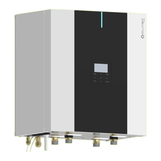
Presentation of the product 4. Presentation of the product Identification Description The serial number label is positioned on the unit and allows Wall-mounted Refrigerant-split heat pump indoor unit. to indentify all the unit features. The matriculation plate shows the indications foreseen by Combinations the standards, in particular: Outdoor unit that can be combined:... -
Page 18: Main Components
Presentation of the product Main components Component Flow switch System circulator Sludge System pressure relief valve DHW / system production valve Vent System exchanger System expansion tank The images are provided for illustrative purposes only. -
Page 19: Components Supplied With The Unit
Presentation of the product Components supplied with the unit A Position of components supplied with the unit The following components can be found in the package: Description Quantity Installation and maintenance manual Water filter Fittings to be welded TORX key Copper reduction 10-6 Insert Compatible accessories... -
Page 20: Before Installation
Before installation 5. Before installation Prerequisites Storage Respect the indications on the outside of the pack. This section is intended exclusively for the Installer. In particolar: Refer to the Technical data chapter for details. • minimum ambient temperature –10 °C •... - Page 21 Before installation Removal of the packaging On reaching the installation site. ► remove the protection elements ► remove the components supplied Carry out the following procedure: ► cut the straps 1 Traps 1 Components supplied 2 Template ► lift and remove the packaging ►...
-
Page 22: Installation
Installation 6. Installation Prerequisites General diagram This section is intended exclusively for the Installer. Wall installation Refer to the Technical data chapter for details. The electrical system and its components must be desi- gned by a qualified technician who must work according to the rules of good practice and national regulations. -
Page 23: Clearances
Installation Clearances Access to internal parts The clearances for installation and maintenance of the unit The unit has removable access panels. are shown in the figure. ► unscrew the fixing screws ► remove the access panel Keypad wire connected... -
Page 24: Access To The Electrical Panel
Installation Access to the electrical panel To access the components behind the electrical panel: ► unscrew the knobs To access the electrical panel: ► unscrew the fixing screws ► remove the electrical panel access panel 1 Knobs ► rotate the electrical panel 1 Electrical panel access panel To refit: ►... -
Page 25: Water Connections
Water connections 7. Water connections General system diagram example The system components must be defined by the Designer and Installer Indispensabile components system (not supplied) C.C. Components provided by Customer DHW exchanger supply (with optional storage tank) System valve DHW exchanger return (with optional storage tank) DHW tank (accessory supplied separately) Water return from system Elfosun 2 (option) -
Page 26: Prerequisites
Water connections Prerequisites Water characteristics The quality of the water used must be in accordance with the This section is intended exclusively for the Installer. requirements in the following table, otherwise a treatment system must be provided. Refer to the Technical data chapter for details. Water component for corrosion limit on Copper Follow the safety instructions in the “About R-32 refrige- PH (25°C) -
Page 27: Piping Insulation
Water connections If necessary, install an additional filter sized according to the type of pollutant to be removed. Piping insulation Isolate the entire hydraulic circuit, including all components to avoid: • the formation of condensation during cooling • the reduction of heating and cooling capacity •... -
Page 28: Hydraulic Connection
Water connections 7.10 Hydraulic connection Ensure that: • clean piping with no moisture, air, dirt or dust is used • the end of the pipe is kept downwards when removing burrs • the end of the pipe is covered when passing it through a wall to prevent dust and dirt from entering •... -
Page 29: Dhw Safety Valve
Water connections 7.13 DHW safety valve 7.14 Relief valves Install them at all the highest points of the piping in order to Inside the unit there is a pressure relief valve (6 bar on vent air from the circuit. the system circuit) which must be connected to a suitable drain, otherwise if the valve trips and floods the rooms, 7.15 Loading the plant the heat pump manufacturer will not be liable. - Page 30 Water connections Repeat this operation after the unit has been operating for a few hours. Check the system pressure periodically. Reintegration is carried out when the unit is off (pump OFF). ► press on the lever and move it to the centre until it locks If the system remains charged and inoperative at outside temperatures close to zero, freezing problems may occur.
-
Page 31: Refrigerant Connections
Refrigerant connections 8. Refrigerant connections Prerequisites etc.), attention is paid to the possibility of installing refri- gerant traps, i.e. closed upstream and downstream areas where the refrigerant cannot expand freely This section is intended exclusively for the Installer. • in this situation, the expansion of the trapped gas Refer to the Technical data chapter for details. - Page 32 Refrigerant connections Connection For refrigerant connection operations, refer to the ma- nual for the combined outdoor unit. 8.2.1 Refrigerant fittings 1 Liquid line 2 Gas line Refrigerant piping size Size 2.1-8.1 Liquid fitting 3/8” * Gas fitting 5/8” * Reduction 10-6 required for size 2.1-3.1 outdoor units, supplied Tightening torque Tightening torque...
-
Page 33: Electrical Connections
Electrical connections 9. Electrical connections Prerequisites The current required for each external load must be less than 0.2 A. If the current required for a single load is gre- ater than 0.2 A, insert a contactor for control. This section is intended exclusively for the Installer. Install an earth leakage breaker (30 mA). -
Page 34: General Diagram
Refrigerant connections General diagram Max 50m Probes Pumps Valves Resistance Backup heater Boiler Bus connection Connections to be provided by customer... -
Page 35: Cable Inlet
Refrigerant connections Cable inlet Connecting the power supply To access the panel, see the “Access to internal parts” section Ensure that: Before removing the protection panel from the electrical • no cables of different cross-sections are connected to panel, disconnect the power supply to the indoor and the same power supply terminal block (loosening of the outdoor units and to all the other electrically powered components. - Page 36 Refrigerant connections 9.4.3 Electric cable sizes Standard Units Unit Maximum overcurrent 16 A protection (MOP) 9,5 A Cable cross-section Units with IBH Unit Maximum overcurrent 25 A 16 A protection (MOP) 18 A 14 A Cable cross-section Cightening torques Tightening torque (N•m) M4 (power terminal, electric from 1.2 to 1.4 control board terminal)
-
Page 37: External Component Connections
Refrigerant connections External component connections Ref. Terminal block CN11 Solar input Dry contact Room thermostat Dry contact (220V) 1OFF Dry contact DHW 3-way valve 2OFF Dry contact 2-way zone valve pump P_c (zone2) Dry contact Pump P_o (zone1) Dry contact Solar pump Dry contact DHW recirculation pump... - Page 38 Refrigerant connections Ref. Terminal block CN11 Dry contact Zone 2 3-way mixing valve Ref. Terminal block CN7 Unit in operation signal Dry contact DFT2 Defrosting status or alarm status Dry contact DFT1 Antifreeze heater for piping Dry contact AHS1 Additional boiler Dry contact AHS2 Ref.
-
Page 39: Bus Connection
Refrigerant connections External electrical components KM..., Fuses, etc. are to be 9.5.3 Double zone mixed system provided by the customer. 9.5.1 Bus connection CN11 CN11 CN11 thermostat thermostat CN11 CN15 Cable type 9.5.4 Antifreeze heater for piping 2-core shielded cable 0.75 - 1.25 mm (AWG18-AWG16) 9.5.2 1-zone system Contact type... - Page 40 Refrigerant connections 9.5.5 Integration heating elements STD connection Optional connection 1 2 3 1 2 3 Heating mode DHW mode Integrated on the unit. 9.5.6 Defrosting status or alarm status DFT1 DFT2 Fuse Contact type 220-240 VAC Maximum tripping of protections (A) Cable cross-section (mm 0.75...
-
Page 41: Backup Heater (Fe Boiler)
Refrigerant connections Backup heater (UC boiler) BOILER BOILER Boiler T1 = Outlet water temperature probe TA2 = room thermostat TA1/OT = remote controller Outdoor temperature probe * (supplied with the boiler) Boiler No Boiler YES Boiler YES ON Dip ON Dip ON Dip DHW and system System integration /... -
Page 42: Zone Thermostat
Refrigerant connections Zone thermostat ON/OFF, user interface managing the unit's mode change. The zone thermostat (to be supplied separately: use the The indoor unit is connected with two room temperature Manufacturer's accessory or equivalent) can be connected thermostats. in three different ways. The choice of which one to use •... -
Page 43: Smart Grid - Photovoltaic Management
Refrigerant connections SMART GRID - Photovoltaic management The smart grid system allows the excess electricity produced by the photovoltaic system or the electricity distribution network to be used to accumulate domestic hot water at lower or no cost. The function can be used with enabled electricity distribution networks. CN33 SMART GRID SMART GRID... -
Page 44: Control4 Ngr
Refrigerant connections 9.10 Control4 NGR Option For details, see Control4 NRG instruction manual. Unità Tastiera Settings FOR SERVICEMAN > 17 HMI ADDRESS SET > 17.2 HMI ADDRESS FOR BMS = 2. Modbus connection Baud rate = 9600 Length = 8 Parity = none Stop bit = 1... -
Page 45: Starting Up The System
Starting up the system 10. Starting up the system This section is intended only for the Technical Support Service. The electrical and hydraulic connections and other works typical of the system are the responsibility of the Installer. Operate in compliance with safety regulations in force. Upon request, the service centres performing the start- Agree upon in advance the star-up data with the servi- ce centre. -
Page 46: Preliminary Checks
Starting up the system 10.1 Preliminary checks For details refer to the different manual sections. 10.1.6.1 Unit power supply: OFF Clearances: • check that distances are observed Refrigerant piping characteristics: • check that the refrigerant piping section is correct • check that the fitting provided are used •... -
Page 47: System Configuration
Starting up the system Fuses, circuit breakers or protection devices: • check that the size and type comply with the instructions in this manual • ensure that no fuses or protective devices have been bypassed Automatic switch of integrative electric heater: •... -
Page 48: Start-Up
Start-up 11. Start-up temperature Preliminary warnings Do not start the compressor with carter oil not in tempe- For system configuration, of advanced features, refer to ratureTensioni the user interface manual. 11.2 Opening the “For serviceman” menu When the unit is turned on, nothing is displayed on the user interface. -
Page 49: Start-Up Report
Start-up • cooling mode • heating mode • DHW mode To verify: ► access the "For serviceman" menu ► Select “Test run” ► press OK ○ the confirmation page is displayed ► select YES ► press OK ► select the operation mode ►... -
Page 50: Maintenance
Maintenance 12. Maintenance 12.1 Prerequisites This section is intended only for the Technical Support Service. All operations must be carried out by personnel who meet the requirements of current regulations and are trained in the risks related to such operations. Operate in compliance with safety regulations in force. -
Page 51: Maintenance Checklist
Maintenance 12.2 Maintenance check list Intervention frequency (months) panel fixing outdoor unit fan fixing outdoor unit coil cleaning hydraulic system filling pressure fittings, caps and wells tightening visual leak check on solar panel fittings air in the piping flow switch / differential pressure switch operation drain dirt separator anode check power remote controls status... -
Page 52: Unit Booklet
Maintenance 12.3 Unit booklet These substances can attack the surface of the product and lead to the formation of cracks and, over time, to the It’s advisable to create a unit booklet to take notes of the possibility of breakage of the plastic material. unit interventions. -
Page 53: Magnetic Sludge
Maintenance damage The glycol solution must be disposed of in accordance with the local laws and regulations in force. 12.13 Magnetic sludge Magnetic filter separates the impurities (sand particles, rust ... etc) present in the system water. The impurities are collected in a settling chamber. Cleaning the filter can also be done with a working system. -
Page 54: Safety Valve
Maintenance 12.14 Safety valve 12.15 Valve motor assembly Almost all losses are caused by impurities deposited inside Should the motor be disassembled from the valve body, the valve. reassemble it following the instructions. ► check the safety valve for leakage Ensure that: ►... -
Page 55: Outdoor Unit Fan
Maintenance 12.16 Outdoor unit fan External unit Check: ► that the fan and its protection grilles are fixed properly ► the fan bearings (anomalies are indicated by abnormal noise and vibrations) ► the terminal protection covers are closed and the cable holders are properly positioned Access to the fan ►... -
Page 56: Decommissioning
Decommissioning 13. Decommissioning 13.1 Disconnection of which are to be collected; • mechanical and electrical parts to be separated and Before performing any work, carefully read: SAFETY disposed of as authorised. WAR-NINGS FOR OPERATIONS ON UNITS CONTAINING When machine components to be replaced for maintenance R-32 purposes are removed or when the entire unit reaches the end of its life and needs to be removed from the installation,... -
Page 57: Residual Risks
Residual risks 14. Residual risks 14.1 General 14.4.1 General risks In this section the most common situations are indicated,as Smell of burning, smoke or other signals of serious these cannot be controlled by the manufacturer and could anomalies may indicate a situation which could cause be a source of risk situations for people or things. -
Page 58: Moving Parts
Residual risks When the metallic mass of the unit is under voltage and is Defects in tubing, the attachments or the removal parts not correctly connected to the earthing system it may be may cause a leak or water projection with the consequent as source of electric shock and electrocution. -
Page 59: Advanced Applications
Advanced applications 15. Advanced applications 15.1 Units connected in cascade Cascade operation allows up to 6 units to be connected in parallel, thereby ensuring that the system is fully reliable and effi- cient. The Master unit controls and displays the parameters of the entire system on its User Interface, activating the Slave units when its capacity is not enough to fulfil the system load. - Page 60 Residual risks Cooling, Heating and DHW logic red to the system in case of problems. It is therefore advisable to copy that set on the master to The unit’s control system can monitor and display the opera- the back-up master on a regular basis to prevent loss of the tions of the entire system only by connecting the Master unit desired settings.
- Page 61 Residual risks • enter the address and press “UNLOCK” to confirm. • power off the Slave unit and remove the HMI from the unit. Connections SLAVE Unit MASTER Unit Use shielded wire, the shielding layer must be earthed Heater for network termi- nation on last unit On/Off switch FUSE...
- Page 62 Residual risks...
-
Page 63: Technical Data
Technical data 16. Technical data SIZE 6.1* 7.1* 8.1* Heating Air 7°C - Water 35°C Nominal heating capacity / max 4,32 / 6,26 6,18 / 7,41 8,30 / 9,11 10,09 / 10,3 12,13 / 14,60 14,51 / 15,5 16,01 / 16,80 Total power input 0,80 1,19... - Page 64 Technical data SIZE 6.1* 7.1* 8.1* Average climatic conditions - Heat pump for Average temperature application Nominal power SCOP 3.32 3.54 3.72 3.73 3.56 3.52 3.48 Generator energy class ηs System energy class ηs Average climatic conditions - Heat pump for Low temperature application Nominal power SCOP 5,13...
- Page 65 Technical data Construction characteristics - Indoor unit SIZE System characteristics Maximum system pressure System expansion tank Expansion tank pre-charge System water connections inch Dimensions Operation (L x W x H) 547 x 386 x 604 547 x 386 x 604 Packaging (L x W x H) 720 x 600 x 550 720 x 600 x 550...
- Page 66 Technical data Outdoor unit sound levels Standard mode Sound power level Sound pressure Sound power level level SIZES Octave band (Hz) 1000 2000 4000 8000 dB(A) dB(A) Sound levels refer to a unit at full load, under nominal test conditions. Data referring to the following conditions: user side exchanger water inlet/outlet 47/55°C source side exchanger air inlet 7°C.
-
Page 67: Operating Range
Technical data Operating range Cooling Twu [°C] = Temperature of the outlet water from the exchanger Tae [°C] = External exchanger inlet air temperature Normal operating range Heating Twu [°C] = Temperature of the outlet water from the exchanger Tae [°C] = External exchanger inlet air temperature 1. - Page 68 Technical data Dimensional Internal unit Electrical panel Unit control keypad Power input Condensation drain 18mm Functional spaces DHW exchanger supply 1" DHW exchanger return 1" Supply to user side system 1" Return to the user side system 1" 10. Gas line (5/8" G) 11.
-
Page 69: External Unit
Technical data External unit Sizes 2.1-3.1 Compressor compartment Electrical panel Power input Condensate drain Gas connections (5/8") Gas connections (1/4") Functional spaces Electric fan SIZE W1 Point of Support 23,9 23,9 W2 Point of Support 13,8 13,8 W3 Point of Support 12,9 12,9 W4 Point of Support... - Page 70 Technical data External unit Sizes 4.1-8.1 1104 Compressor compartment Electrical panel Power input Condensate drain Gas connections (3/8") Gas connections (5/8") Functional spaces Electric fan SIZE 4.1 / 1PH 5.1 / 1PH 6.1 / 1PH 6.1 / 3PH 7.1 / 1PH 7.1 / 3PH 8.1 / 1PH 8.1 / 3PH...
-
Page 71: Energy Labels
Energy labels 17. Energy labels Modello info prodotto /Product info template Information requirements for heat pump space heaters and heat pump combination heaters. Informazioni obbligatorie per gli apparecchi a pompa di calore per il riscaldamento d’ambiente e gli apparecchi di riscaldamento misti a pompa di calore Model(s): / Modelli: Air-to-water heat pump: / Pompa di calore aria/acqua: Water-to-water heat pump: / Pompa di calore acqua/acqua:... - Page 72 Contact details: / CLIVET SPA - VIA CAMP LONC, 25 - Z.I. VILLAPAIERA - 32032 FELTRE (BL) - ITALY Recapiti: (*) For heat pump space heaters and heat pump combination heaters, the rated heat output Prated is equal to the design load for heating Pdesignh, and the rated heat output of a supplementary heater Psup is equal to the supplementary capacity for heating sup(Tj).
- Page 73 Modello scheda prodotto / Product card model Product fiche: combination heaters Scheda prodotto: apparecchi di riscaldamento misti SERIES / Serie Model / Modello Size / Grandezza Medium-temperature application / °C Applicazione a media temperatura Low-temperature application / Applicazione a bassa temperatura °C DHW profile / Profilo ACS Medium-temperature class / Classe a media temperatura...
- Page 74 Product fiche: temperature control / Scheda prodotto: dispositivi di controllo della temperatura SERIES / Serie Model / Modello Size / Grandezza Device class ɳ s Product fiche: packages of combination heater, temperature control and solar device / Scheda prodotto: insiemi di apparecchi di riscaldamento misti, dispositivi di controllo della temperature e dispositivi solari Control class T / Classe controllo T ɳ...
- Page 75 Media temperatura / medium-temperature Description Symbol SQKN-YEE 1 BC SQKN-YEE 1 BC SQKN-YEE 1 BC SQKN-YEE 1 BC SQKN-YEE 1 BC SQKN-YEE 1 BC SQKN-YEE 1 BC Model(s): / Modelli: MiSAN-YEE 1 S 2.1 MiSAN-YEE 1 S 3.1 MiSAN-YEE 1 S 4.1 MiSAN-YEE 1 S 5.1 MiSAN-YEE 1 S 6.1 MiSAN-YEE 1 S 7.1...
- Page 76 Description Symbol SPHERA EVO 2.0 SPHERA EVO 2.0 SPHERA EVO 2.0 SPHERA EVO 2.0 SPHERA EVO 2.0 SPHERA EVO 2.0 SPHERA EVO 2.0 SERIES / Serie SQKN-YEE 1 BC SQKN-YEE 1 BC SQKN-YEE 1 BC SQKN-YEE 1 BC SQKN-YEE 1 BC SQKN-YEE 1 BC SQKN-YEE 1 BC Model / Modello...
- Page 77 Bassa temperatura / low-temperature Description Symbol SQKN-YEE 1 BC SQKN-YEE 1 BC SQKN-YEE 1 BC SQKN-YEE 1 BC SQKN-YEE 1 BC SQKN-YEE 1 BC SQKN-YEE 1 BC Model(s): / Modelli: MiSAN-YEE 1 S 2.1 MiSAN-YEE 1 S 3.1 MiSAN-YEE 1 S 4.1 MiSAN-YEE 1 S 5.1 MiSAN-YEE 1 S 6.1 MiSAN-YEE 1 S 7.1...
- Page 78 Description Symbol SPHERA EVO 2.0 SPHERA EVO 2.0 SPHERA EVO 2.0 SPHERA EVO 2.0 SPHERA EVO 2.0 SPHERA EVO 2.0 SPHERA EVO 2.0 SERIES / Serie SQKN-YEE 1 BC SQKN-YEE 1 BC SQKN-YEE 1 BC SQKN-YEE 1 BC SQKN-YEE 1 BC SQKN-YEE 1 BC SQKN-YEE 1 BC MiSAN-YEE 1 S...
- Page 79 Dati tecnici per soluzione ibrida, sostituiscono i dati delle tabelle precedenti / Technical data for hybrid solution, replace the data in the previous tables 24,2 24,4 34,4 Description Symbol Equipped with a supplementary heater: / Con riscaldatore supplementare: Rated heat output (*) / Potenza termica nominale (*) Prated Seasonal space heating energy efficiency /...
- Page 94 Notes...
- Page 95 Notes...
- Page 96 FOR OVER 30 YEARS, WE HAVE BEEN OFFERING SOLUTIONS TO ENSURE SUSTAINABLE COMFORT AND THE WELL-BEING OF PEOPLE AND THE ENVIRONMENT sales and assistance Info & Contacts: www.clivet.com...
Need help?
Do you have a question about the SPHERA EVO 2.0 Box and is the answer not in the manual?
Questions and answers