Table of Contents
Advertisement
Quick Links
Advertisement
Table of Contents

Related Manuals for Ametek Jofra CTC-350 A/C


Summary of Contents for Ametek Jofra CTC-350 A/C
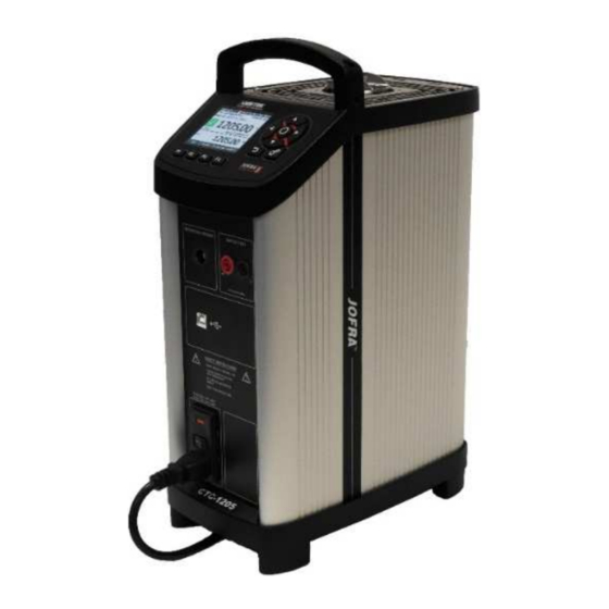
- Page 1 User Manual Compact Temperature Calibrator Jofra CTC-155/350/660/1205 A/C...
- Page 2 User Manual Compact Temperature Calibrator JOFRA CTC-155/350/660/1205 A/C Copyright 2016 AMETEK Denmark A/S...
-
Page 3: Table Of Contents
List of contents 1.0 Introduction ........................3 1.1 List of equipment received………………………………………………………………………… 3 2.0 Safety instructions ......................4 3.0 Setting up the calibrator ....................7 3.1 Before use……………………………………………………………………………………….….. 7 3.2 Keypad - Functions…………………………………………………………………………………. 9 3.3 Display…………………………………………………………………………………………….. 10 3.4 Connections……………………………………………………………………………………… 11 3.5 Stability of temperature values……………………………………………………………………... -
Page 4: Introduction
Introduction CTC-calibrators are temperature calibrators designed to calibrate temperature sensors and temperature switches. Read this manual carefully before using the instrument and make sure that all safety instructions and warnings are observed. List of equipment received When you receive the instrument, the following should be enclosed: •... -
Page 5: Safety Instructions
Safety instructions Read this manual carefully before using the instrument! In order to avoid any personal injuries and/or damage to the instrument all safety instructions and warnings must be observed. Disposal – WEEE Directive These calibrators contain Electrical and Electronic circuits and must be recycled or disposed of properly (in accordance with the WEEE Directive 2012/19/EU). - Page 6 50°C/122°F before placing it in the carrying case. • Never place a hot insertion tube in the optional carrying case. • Use only insulation plugs supplied by AMETEK Denmark A/S. • Never try to modify the insulation plugs to make them fit the sensor (CTC-1205...
- Page 7 To prevent this from happening the insertion tube and the well must be dried. This is done by heating up the calibrator to 100°C/212°F until all water left has evaporated. Remove the insulation plug while heating up. It is very important that humidity in the well and insertion tube is removed to prevent corrosion and frost expansion damages.
-
Page 8: Setting Up The Calibrator
Setting up the calibrator ENVIRONMENTAL SPECIFICATIONS Ambient operating temperature range: 0-50°C / 32-122°F Storage temperature range: -20-50°C / -4-122°F Humidity range: 5-90% RH, non-condensing IP protection class: IP10 Altitude: 0-2000 m / 0-3000 m (CTC-1205 only) Electromagnetic Compatibility: Tested for use in domestic establishment and in establishments directly connected to low voltage power supply network which supplies buildings used for domestic purposes as well as in an... - Page 9 • The calibrator must be kept clear within an area of 20 cm on all sides and 1 metre above the calibrator due to fire hazard. • Use only insulation plugs supplied by AMETEK Denmark A/S. • Never try to modify the insulation plugs to make them fit the sensor (CTC-1205 only) Caution –...
- Page 10 Check that the earth connection for the instrument is present and attach the cable. Place the sensor (pos. 3) in the insertion tube (pos. 4) as shown in the figure below. Caution… Before using new insertion tubes for the calibration in the CTC-350/660/1205 instruments the insertion tubes must be heated up to maximum temperature 350°C(662°F) / 660°C (1220°F) / 1205°C (2201°F) for a period of minimum 30 minutes.
-
Page 11: Keypad - Functions
Keypad - Functions Function keys - F1, F2, F3, F4 For operating the horizontal menu. Arrow Keys Navigation mode: Use the four keys to move the cursor in the desired direction. Edit mode: The Up and Down Arrow keys scroll through the lists of options. -
Page 12: Connections
4) Reference sensor info Shows the reference sensor selected. The serial number of the external reference sensor is read from the intelligent reference sensor and displayed in this field. 5) Memory reading Shows the current memory selected from the System menu. 6) Warning/Error symbols. - Page 13 • Indicates that the “stable” situation is achieved and for how long the calibrator has been stable. When the calibrator has been stable for more than 99 minutes, only the stable sign is displayed (time is no longer displayed). • If External reference is selected as TRUE, the stability criteria will refer to this.
-
Page 14: 4.0 Operating The Calibrator
4.0 Operating the calibrator Operating principle The calibrator is operated using the Functions keys, the Arrow keys and the Action/Enter key. 1. Press the Functions keys to operate the horizontal menu bar. 2. Press any of the (Arrow) keys to enter Navigation Mode. Editable fields will be highlighted in blue. - Page 15 Note… • If the current set-temperature is higher than the new max-temperature, you will need to adjust the set-temperature. The instrument will immediately begin to cool (if required) as soon as the new max-temperature is accepted. • The calibration interval can be set between 1 and 99 months. When the calibration interval is exceeded, a yellow warning symbol will appear in the upper part of the display.
-
Page 16: Starting The Calibrator
• Store menu (Save Settings) After you have configured the instrument, you can save the setup for future use using the Store function. 1. Use the (Up) and (Down) Arrow keys to select the Memory-setup you want to modify, and press (Save). -
Page 17: Selecting A True - Reference Sensor (C-Models Only)
Selecting a TRUE – reference sensor (C-models only) 1. Press one of the (Arrow) keys and the (Enter) key to access the Mode menu. You can choose between one of the following sensor constellations: • Internal reference source (A and C models) •... -
Page 18: Stability Setting
Note… that when “SET follow true” is selected, the calibrator will control the temperature to the TRUE temperature. This means that it could take longer time before the calibrator indicates stability. Stability setting True: Internal reference When internal reference is selected the calibrator uses a set of minimum internal stability criteria that shall be met before stability is indicated. -
Page 19: Editing The Preset Set-Temperature
1. For selecting the preset temperature press (Preset). 2. Select one of the 4 temperature options available from the menu bar by pressing the correspondent Function key (F1 – F4). 3. The set-temperature is selected, once the Function key has been pressed. The calibrator will now heat up / cool down. -
Page 20: Auto Step Function
4. Press (Enter) to access the editable field and use the arrows (Up) and (Down) to select a new set value. 5. Press (Enter) to accept the new set value. 6. Press (Back) to return to the previous menu. Auto Step function Auto Step is used to step automatically between a range of different calibration temperatures. -
Page 21: The Calibrator's Auto Step Procedure
3. Press (F4) to start the Auto Step test. The Auto Step test is now in progress. While the Auto Step test is in progress, 4 options are available: • Stop : Press (F1) to stop the Auto Step test. The process will end. -
Page 22: Switch Test Function
Switch Test function Switch Test automatically locates the switch temperature of a thermostat. Three parameters are required: • Start temperature (T • End temperature (T • Rate of change in temperature pr. minute (Rate). Dead band of a thermostat can also be determined here. Where the dead band determines the tolerance between the upper switch temperature and the lower switch temperature of the thermostat. -
Page 23: The Calibrator's Switch Test Procedure
2. Press one of the (Arrow) keys to access the editable fields for new values: • T First set temperature • T Second set temperature • Dead band : To determine dead band, toggle between "Yes" (a two-way- temperature measurement) and "No" (a one-way-temperature measurement). - Page 24 5) When dead band is not selected (single temperature change) (the graphic indicates the choice), the finished switch test result is displayed. When dead band is selected (two switch changes), the calibrator starts working towards T at the specified Rate. 6) Normally, the thermostat changes state before T is achieved.
-
Page 25: Setting The Mains Voltage And Replacing The Main Fuses
Setting the mains voltage and replacing the main fuses Replacing the main fuses Warning • The calibrator must be switched off before any attempt to service the instrument is made. There are no user serviceable parts inside the calibrator. • The fuse box must not be removed from the power control switch until the mains cable has been disconnected. -
Page 26: After Use
After use Storing and transporting the calibrator Caution… The following guidelines should always be observed when storing and transporting the calibrator. This will ensure that the instrument and the sensor remain in good working order. Warning • The calibrator must be switched off before any attempt to service the instrument is made. -
Page 27: Switching Off The Calibrator
Switching off the calibrator 1. Switch off the calibrator using the power control switch. Note that the calibration procedure may be interrupted at any time using the power control switch. Switching off the calibrator during the calibration process will not damage either the instrument or the sensor. 2. - Page 28 • If the calibrator is to be transported long distances, the insertion tube must be removed from the well to avoid damage to the instrument. If the insertion tube is not removed from the CTC-1205 the ceramic well might crack. Warning •...
- Page 29 Tel +86 10 8526 2111 Tel +49 (0)2159 9136 510 India jofra-china.sales@ametek.com.cn info.mct-de@ametek.de Tel +91 22 2836 4750 jofra@ametek.com Denmark Tel +45 4816 8000 jofra@ametek.com Information in this document is subject to change without notice. ©2017 by AMETEK, Inc., www.ametek.com. All rights reserved.
Need help?
Do you have a question about the Jofra CTC-350 A/C and is the answer not in the manual?
Questions and answers