Advertisement
Quick Links
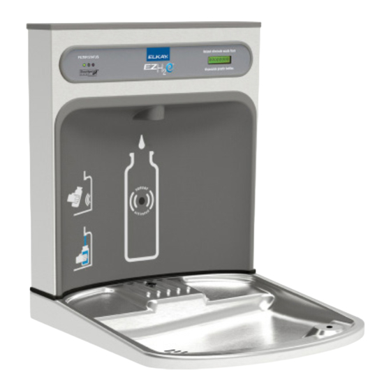
EZWSRK - ezH2O
LZWSRK - ezH2O
IMPORTANT! INSTALLER PLEASE NOTE.
THE GROUNDING OF ELECTRICAL EQUIPMENT SUCH AS TELEPHONE, COMPUTERS, ETC. TO WATER LINES
IS A COMMON PROCEDURE. THIS GROUNDING MAY BE IN THE BUILDING OR MAY OCCUR AWAY FROM
THE BUILDING. THIS GROUNDING CAN CAUSE ELECTRICAL FEEDBACK INTO A FOUNTAIN, CREATING AN
ELECTROLYSIS WHICH CAUSES A METALLIC TASTE OR AN INCREASE IN THE METAL CONTENT OF THE
WATER. THIS CONDITION IS AVOIDABLE BY USING THE PROPER MATERIALS AS INDICATED. ANY DRAIN
FITTINGS PROVIDED BY THE INSTALLER SHOULD BE MADE OF PLASTIC TO ELECTRICALLY ISOLATE THE
FOUNTAIN FROM THE BUILDING PLUMBING SYSTEM. WE SUGGEST THAT THE BOTTLE FILLING STATION
AND WATER COOLER BE PROTECTED BY A GROUND FAULT CIRCUIT INTERRUPTER (GFCI).
INSTALLER
EZWSR / LZWSR Bottle Fillers are among the easiest to install on the market today.
To insure you install these models easily and correctly, PLEASE READ THESE
SIMPLE INSTRUCTIONS BEFORE STARTING THE INSTALLATION. CHECK
YOUR INSTALLATION FOR COMPLIANCE WITH PLUMBING, ELECTRICAL, AND
OTHER APPLICABLE CODES. After installation, leave these instructions with the
Cooler for future reference.
EZWSR*1D, *2D
LZWSR*1D, *2D
R
-F
®
ETRO
R
-F
®
ETRO
THIS IS AN INDOOR APPLICATION ONLY.
ALL SERVICE TO BE PERFORMED BY AN
SAFETY GLASSES
GLOVES
3/4" WRENCH OR CRESCENT
WRENCH
5/16" NUT DRIVER
UTILITY KNIFE
TAPE MEASURE
PENCIL
CENTER PUNCH
1/2" SOCKET & RATCHET WRENCH
5/32" ALLEN WRENCH
7/64" ALLEN WRENCH
Page 1
WWW.RESTROOMDIRECT.COM
INSTALLATION & USE MANUAL
B
F
IT
OTTLE
ILLING
B
F
IT
OTTLE
ILLING
IMPORTANT
AUTHORIZED SERVICE PERSON.
TOOLS REQUIRED
BUT NOT PROVIDED:
704 • 937• 2673
129 Oakpark Dr., Unit A, Mooresville, NC 28115
U
NIT
U
NIT
1000004729 (Rev. A - 09/18)
Advertisement

Related Manuals for Elkay ezH2O LZWSR 1D Series


Summarization of Contents
Important Information and Installer Notes
Tools Required for Installation
Lists tools needed for installation.
Installer Notes and Code Compliance
Guidance for installers on reading instructions and code compliance.
Water Cooler Preparation Steps
EWF3000 Watersentry Plus Filter Installation
Instructions for installing the EWF3000 Watersentry Plus filter.
Water System Pressurization Procedure
Steps to pressurize the water system for proper operation.
Standard Bi-Level Models Modification
Modifications for standard bi-level water systems.
Bi-Level Versatile Models Modification
Modifications for bi-level versatile water systems.
Standard Rough-In Dimensions
ADA Cooler Height Reduction Note
Note regarding height adjustment for ADA compliant installations.
Plumbing Diagrams for EZ Models
EZ Non-Pressurized Plumbing
Plumbing diagram for non-pressurized EZ models.
EZ Plumbing After Pressurization Modifications
Plumbing diagram after pressurization modifications.
Standard Bi-Level Pressurized Plumbing
Plumbing diagram for standard bi-level pressurized models.
EZ Bi-Level Plumbing Water Line Addition
Plumbing diagram for bi-level after water line addition.
Plumbing Diagrams for EZ Coolers (Models 1, 1A, 2, 3)
EZ Non-Pressurized Plumbing (Fig. 6B)
Plumbing diagram for EZ models ending in 1, 1A, 2, or 3.
EZ Plumbing After Pressurization (Fig. 7B)
Plumbing diagram after pressurization for specific EZ models.
Standard Bi-Level Pressurized Plumbing (Fig. 6C)
Plumbing diagram for standard bi-level pressurized models.
EZ Bi-Level Plumbing Addition (Fig. 7C)
Plumbing diagram for bi-level after water line addition.
Plumbing Diagrams for EZ Models (Continued)
EZ Non-Pressurized Plumbing (Fig. 6D)
Plumbing diagram for non-pressurized EZ models.
EZ Plumbing After Filter Installation
Plumbing diagram after filter and pressurization modifications.
Standard Bi-Level Pressurized Plumbing (Fig. 6E)
Plumbing diagram for standard bi-level pressurized models.
EZ Bi-Level Plumbing Addition (Fig. 7E)
Bi-level plumbing diagram after filter and water line addition.
Plumbing Diagrams for EZ Coolers (Models 1, 1A, 2, 3 - Continued)
EZ Non-Pressurized Plumbing (Fig. 6F)
Plumbing diagram for EZ models ending in 1, 1A, 2, or 3.
EZ Plumbing After Filter Installation (Fig. 7F)
Plumbing diagram after filter and pressurization modifications.
Standard Bi-Level Pressurized Plumbing (Fig. 6G)
Plumbing diagram for standard bi-level pressurized models.
EZ Bi-Level Plumbing Addition (Fig. 7G)
Bi-level plumbing diagram after filter and water line addition.
Basin Assembly Preparation
Quick Connect Fittings Operation
Illustrates how to use quick connect fittings for tubing.
Wiring Diagrams
Bottle Filler 115V Wiring
Wiring diagram for the 115V bottle filler unit.
Non-Refrigerated Side Wiring
Wiring diagram for the non-refrigerated side of the unit.
Refrigerated Side Wiring
Wiring diagram for the refrigerated side of the unit.
Bottle Filler Installation
Quick Connect Fittings Operation
Illustrates how to use quick connect fittings for tubing.
Control Board Settings Configuration
Verify Control Board Software
Procedure to verify the control board software version.
Access Programming Button
Steps to access the programming button and control board settings.
Reset Filter Monitor
Instructions to reset the visual filter monitor indicator.
Set IR Sensor Range
Configuration for the IR sensor range for dispensing.
Set Unit Type
Setting the unit type as refrigerated or non-refrigerated.
Reset Bottle Count
Procedure to reset the bottle count display to zero.
Set Filter Capacity
Configuration for the filter capacity setting.
Need help?
Do you have a question about the ezH2O LZWSR 1D Series and is the answer not in the manual?
Questions and answers