Table of Contents
Advertisement
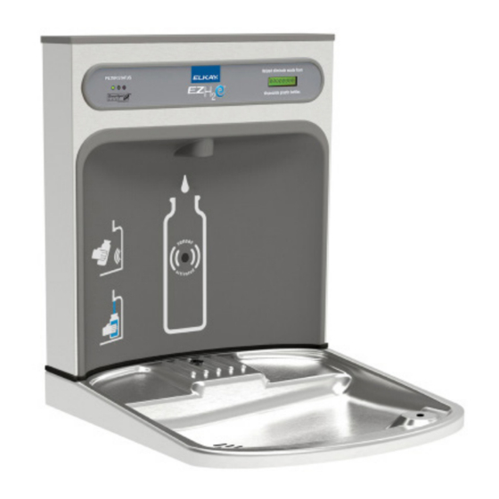
EZWSRK -EZH
LZWSRK -EZH
THE GROUNDING OF ELECTRICAL EQUIPMENT SUCH AS TELEPHONE, COMPUTERS, ETC. TO WATER LINES
IS A COMMON PROCEDURE. THIS GROUNDING MAY BE IN THE BUILDING OR MAY OCCUR AWAY FROM
THE BUILDING. THIS GROUNDING CAN CAUSE ELECTRICAL FEEDBACK INTO A FOUNTAIN, CREATING AN
ELECTROLYSIS WHICH CAUSES A METALLIC TASTE OR AN INCREASE IN THE METAL CONTENT OF THE
WATER. THIS CONDITION IS AVOIDABLE BY USING THE PROPER MATERIALS AS INDICATED. ANY DRAIN
FITTINGS PROVIDED BY THE INSTALLER SHOULD BE MADE OF PLASTIC TO ELECTRICALLY ISOLATE THE
FOUNTAIN FROM THE BUILDING PLUMBING SYSTEM. WE SUGGEST THAT THE BOTTLE FILLING STATION
AND WATER COOLER BE PROTECTED BY A GROUND FAULT CIRCUIT INTERRUPTER (GFCI).
INSTALLER
EZWSR / LZWSR Bottle Fillers are among the easiest to install on the market today.
To insure you install these models easily and correctly, PLEASE READ THESE
SIMPLE INSTRUCTIONS BEFORE STARTING THE INSTALLATION. CHECK
YOUR INSTALLATION FOR COMPLIANCE WITH PLUMBING, ELECTRICAL, AND
OTHER APPLICABLE CODES. After installation, leave these instructions with the
Cooler for future reference.
EZWSR*1C, *2C
O
R
®
2
O
R
®
2
IMPORTANT! INSTALLER PLEASE NOTE.
LZWSR*1C, *2C
INSTALLATION & USE MANUAL
-F
B
ETRO
IT
OTTLE
-F
B
ETRO
IT
OTTLE
IMPORTANT
THIS IS AN INDOOR APPLICATION ONLY.
ALL SERVICE TO BE PERFORMED BY AN
AUTHORIZED SERVICE PERSON.
TOOLS REQUIRED
BUT NOT PROVIDED:
SAFETY GLASSES
GLOVES
3/4" WRENCH OR CRESCENT
WRENCH
5/16" NUT DRIVER
UTILITY KNIFE
TAPE MEASURE
PENCIL
CENTER PUNCH
1/2" SOCKET & RATCHET WRENCH
5/32" ALLEN WRENCH
7/64" ALLEN WRENCH
Page 1
F
U
ILLING
NIT
F
U
ILLING
NIT
1000001734 (Rev. K- 04/18)
Advertisement
Table of Contents

Related Manuals for Elkay EZWSRK-EZH2O


Summarization of Contents
Installer Important Notes and Precautions
Electrical Grounding and Water Quality
Discusses grounding of electrical equipment and its effect on water quality, advising plastic fittings and GFCI.
Pre-Installation Checks and Compliance
Emphasizes reading instructions, checking plumbing, electrical, and other codes before installation.
Water Cooler Preparation and System Setup
Basin Assembly Removal and Filter Installation
Detailed steps for removing the basin assembly and installing the EWF3000 Watersentry Plus filter.
Water System Pressurization and Bi-Level Modification
Procedures for pressurizing the water system and modifying bi-level units for proper operation.
Standard Rough-In Diagram: Left-Hand High, Low Models
Left-Hand High, Low Model Layout Specifications
Diagram detailing dimensions and layout for standard left-hand high, bottle filler low models.
Installation Legend and Safety Requirements
Explains diagram symbols, dimensions, and key installation notes, including GFCI.
Alternate Rough-In Diagram: Right-Hand High, Low Models
Right-Hand High, Low Model Layout Specifications
Diagram detailing dimensions and layout for alternate right-hand high, bottle filler low models.
Installation Legend and Safety Requirements
Explains diagram symbols, dimensions, and key installation notes, including GFCI.
Alternate Rough-In Diagram: Right-Hand High, High Models
Right-Hand High, High Model Layout Specifications
Diagram detailing dimensions and layout for alternate right-hand high, bottle filler high models.
Installation Legend and Safety Requirements
Explains diagram symbols, dimensions, and key installation notes, including GFCI.
Alternate Rough-In Diagram: Left-Hand High, High Models
Left-Hand High, High Model Layout Specifications
Diagram detailing dimensions and layout for alternate left-hand high, bottle filler high models.
Installation Legend and Safety Requirements
Explains diagram symbols, dimensions, and key installation notes, including GFCI.
Plumbing Diagrams: EZ Systems
Non-Pressurized and Pressurized EZ System Plumbing
Diagrams illustrating non-pressurized and pressurized water flow for EZ systems.
Bi-Level System Plumbing Variations
Diagrams for standard and modified bi-level water systems, showing line connections.
Plumbing Diagrams: EZ Coolers (Specific Models)
EZ Cooler Model Plumbing Configurations
Plumbing diagrams for EZ coolers with model numbers ending in 1, 1A, 2, or 3.
Bi-Level Cooler Model Plumbing Configurations
Plumbing diagrams for Bi-Level coolers with specific model number endings.
Plumbing Diagrams: Filtered EZ Systems
EZ System Filter Installation Plumbing
Diagrams showing filter installation and pressurization modifications for EZ systems.
Bi-Level System Filter Installation Plumbing
Diagrams for Bi-Level systems detailing filter installation and water line additions.
Plumbing Diagrams: Filtered EZ Coolers (Specific Models)
EZ Cooler Model Plumbing with Filter
Plumbing diagrams for EZ coolers with filter, specific to model number endings.
Bi-Level Cooler Model Plumbing with Filter
Plumbing diagrams for Bi-Level coolers with filter, specific to model number endings.
Bottle Filler Installation and Final Assembly
Mounting Plate and Bottle Filler Attachment
Detailed steps for attaching the wall mounting plate and securing the bottle filler unit.
Filter Installation and System Testing
Instructions for installing the filter cartridge and performing initial system testing and checks.
Wiring Diagrams and Connections
Bottle Filler 115V Unit Wiring
Comprehensive wiring diagram for the 115V bottle filler unit.
Non-Refrigerated and Refrigerated Side Wiring
Wiring diagrams for the non-refrigerated and refrigerated sections of the bi-level cooler.
Detailed Bottle Filler Installation Steps
Wall Mounting Plate and Unit Attachment
Step-by-step guide for installing the wall mounting plate and connecting the bottle filler.
Water Lines, Wiring, Filter, and Testing
Completing water line connections, wiring, filter installation, and final operational tests.
Bottle Filler Gasket Illustrations
Gasket Placement and Visuals
Visual references showing the bottle filler gasket and its typical placement.
Bi-Level Cooler Wiring Modification
Troubleshooting Bottle Filler Counter Issues
Specific wiring modifications for non-refrigerated bi-level units to correct continuous bottle filler counter advancement.
Plumbing Diagrams for Versatile Bi-Level Units
Versatile Bi-Level Plumbing Configurations
Diagrams illustrating various plumbing setups for versatile bi-level units, showing barb capping.
Control Board Programming and Settings
Software Verification and Access
Procedures to verify the control board's software version and access programming menus.
Unit Type and Filter Capacity Configuration
Settings for unit type (Refrig/Non-Refrig) and filter capacity (e.g., 3000/6000 GAL).
Bottle Counter and Filter Monitor Reset
Instructions to reset the bottle counter and the visual filter monitor status.
Alternate Filter Mounting Location
Drilling and Bracket Installation for Filter
Steps for creating mounting holes and installing the filter bracket.
Filter Assembly and Bushing Installation
Installing the filter assembly and protective bushing for waterlines.
Watersentry Plus Filter Parts and Kits
Filter Components List
Itemized list of components for the Watersentry Plus filter system.
Available Replacement Part Kits
Overview of various replacement part kits for different cooler components.
Need help?
Do you have a question about the EZWSRK-EZH2O and is the answer not in the manual?
Questions and answers