Advertisement
Table of Contents
- 1 Table of Contents
- 2 Introduction
- 3 Specifications
- 4 Blower Data
- 5 Parts Identification
- 6 I Unit Components
- 7 Installation
- 8 Start up
- 9 Preliminary Seasonal Checks
- 10 Heating Start up
- 11 Heating System Service Checks
- 12 Typical Operating Characteristics
- 13 Maintenance
- 14 Wiring and Sequence of Operation
- 15 Surelight Control Troubleshooting
- Download this manual
Service Literature
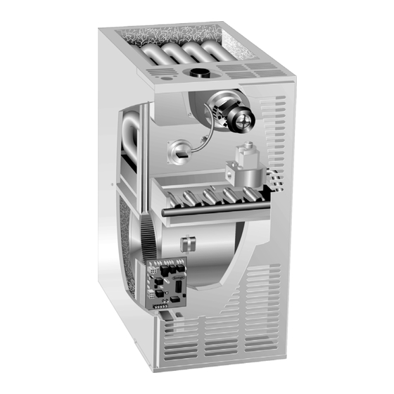
80MGF series units are mid−efficiency gas furnaces
manufactured with tubular heat exchangers formed of alu-
minized or stainless steel. 80MGF units are available in
heating capacities of 45,000 to 140,000 Btuh and cooling
applications up to 5 tons. Refer to Engineering Handbook
for proper sizing.
Units are factory equipped for use with natural gas. A kit is
available for conversion to LPG operation. All 80MGF units
built proir to September 98 use electronic (direct spark) igni-
tion. 80MGF−11 model units are equipped with the Lennox
SureLight ignition system. The 80MGFX unit meets the
California Nitrogen Oxides (NO
Seasonal Efficiency requirements. All units use a redun-
dant gas valve to assure safety shut−off as required by
A.G.A. or C.G.A.
The heat exchanger, burners and manifold assembly can
easily be removed for inspection and service by simply dis-
connecting gas, unplugging wiring harness and spark wires
and removing four screws holding the heat exchanger in
place. Then the heat exchanger slides out of the cabinet.
All specifications in this manual are subject to change.
Procedures outlined in this manual are presented as a rec-
ommendation only and do not supersede or replace local
or state codes. In the absence of local or state codes, the
guidelines and procedures outlined in this manual (except
where noted) are recommended only and do not constitute
code.
Units may be installed in upflow, downflow or horizontal
position. The heat exchanger is designed for upright or
horizontal use only. When the unit is installed in the down-
flow position, the heat exchanger is field removed and re-
installed so it is upright when the cabinet is inverted. No
field conversion is required when the unit is installed in the
horizontal position.
. . . . . . . . . . . . . . . . . . . . . . . .
. . . . . . . . . . . . . . . . . . . . . .
. . . . . . . . . . . . . . . . . . . . . . .
. . . . . . . . . . . . . . . . . .
. . . . . . . . . . . . . . . . . .
. . . . . . . . . . . . . . . . . . . . . . .
80MGF SERIES UNITS
) Standards and California
x
TABLE OF CONTENTS
1
2
5
7
9
19
. . . . . . . . . . . . . . . . . . . . . . . . .
. . . . . . . . . . . . . . . . . . . .
Page 1
80MGF
Corp. 9801−L2
Revised 08−2004
19
. . . . .
20
. . . . . . . . . . . . . . . .
20
. . .
20
. . .
22
24
.
26
.
40
© 1998 Lennox Industries Inc.
Advertisement
Table of Contents

Related Manuals for Lennox 80MGF4/5-120


Summarization of Contents
BLOWER PERFORMANCE DATA (models 2-75)
80MGF2-45, 80MGF2-60 AND 80MGF2-75 BLOWER PERFORMANCE
Performance data for specific 80MGF blower models.
80MGF3-60 AND 80MGF3-75 BLOWER PERFORMANCE
Performance data for specific 80MGF blower models.
BLOWER PERFORMANCE DATA (models 75-140) & FILTER RESISTANCE
80MGF4-75, 80MGF3/4-100 AND 80MGF3/4-120 BLOWER PERFORMANCE
Performance data for specific 80MGF blower models.
80MGF4/5-100, 80MGF4/5-120 AND 80MGF4/5-140 BLOWER PERFORMANCE
Performance data for specific 80MGF blower models.
FILTER AIR RESISTANCE
Table detailing air resistance based on airflow (CFM) and pressure.
UNIT COMPONENTS
Blower Door Components
Details electrical components on the blower access door.
EGC CONTROL (A3)
Ignition Control
Description of the EGC direct spark ignition sequence and safety features.
Blower Operation / Fan Off Timings
Explains fan operation after heat demand and timing adjustments.
COMPONENT DESCRIPTIONS (Ignition & Sensor)
Flame Sensor
Details the flame sensor location, function, and testing.
SureLight Ignition System
Overview of the SureLight ignition system and its components.
COMPONENT SAFETY PROCEDURES
Electrostatic Discharge Precautions
Procedures to prevent damage to electronic components from static discharge.
COMPONENT DESCRIPTIONS (Mechanical)
Blower Motors and Capacitors
Ratings and types of blower motors and capacitors used.
Combustion Air Blower
Function and operation of the combustion air blower.
Flame Rollout Switches
Description and function of the flame rollout safety switches.
Primary Limit Control
Details the primary limit control's function and location.
COMPONENT DESCRIPTIONS (Electrical & Gas)
Secondary Limit Controls
Function and location of secondary limit controls.
Spark Electrode and Flame Sensor
Arrangement and testing of ignition system electrodes.
Gas Valve
Description of the gas valve, its types, and connections.
HEATING SYSTEM SERVICE CHECKS
Preliminary and Seasonal Checks
Initial inspections and checks before operation.
Heating Start-Up
Step-by-step guide for safely starting the furnace.
Safety or Emergency Shutdown
Procedures for safely shutting down the unit in emergencies.
Extended Period Shutdown
Guidelines for shutting down the unit for long-term storage.
TYPICAL OPERATING CHARACTERISTICS
Blower Operation and Adjustment
How blower operation is controlled and adjusted.
Temperature Rise
Factors affecting and how to set temperature rise.
High Altitude Derate
Adjustments required for installations at high altitudes.
Flame Signal
How to measure and interpret the flame signal.
PERFORMANCE TESTING PROCEDURES
Temperature Rise Measurement
Method for measuring temperature difference between return and supply air.
External Static Pressure Measurement
Procedure for measuring static pressure in the duct system.
Blower Speed Taps
How to select and change blower motor speed taps.
MAINTENANCE PROCEDURES
Filters
Filter inspection, cleaning, replacement, and size information.
Cleaning Heat Exchanger and Burners
Instructions for cleaning burners and inspecting the heat exchanger.
Supply Air Blower
Maintenance for the supply air blower motor.
SYSTEM CHECKS AND PROCEDURES
Flue and Chimney
Requirements for flue and chimney installation and inspection.
Electrical Checks
Procedures for checking furnace wiring and voltage.
WIRING AND SEQUENCE OF OPERATION (RAM Control)
80MGF WITH RAM CONTROL
Sequence of operation for furnaces with the RAM control.
TROUBLESHOOTING SEQUENCE (Heating)
NORMAL HEATING MODE
Diagnostic sequence for normal heating operation.
ABNORMAL HEATING MODE
Diagnostic sequence for abnormal heating operation.
WIRING DIAGRAMS (EGC-2 Control)
80MGF WITH EGC-2 IGNITION CONTROL
Wiring and sequence for EGC-2 ignition control.
HEATING SEQUENCE OF OPERATION (EGC-2)
NORMAL HEATING MODE
Normal heating operation sequence for EGC-2 control.
ABNORMAL HEATING MODE
Abnormal heating operation sequence for EGC-2 control.
COOLING AND FAN SEQUENCE OF OPERATION (EGC-2)
80MGF WITH EGC-2 COOLING SEQUENCE OF OPERATION
Cooling sequence for EGC-2 control.
80MGF WITH EGC-2 MANUAL CONTINUOUS FAN SEQUENCE OF OPERATION
Continuous fan sequence for EGC-2 control.
WIRING DIAGRAMS (EGC-1 Control)
80MGF WITH EGC-1 IGNITION CONTROL
Wiring and sequence for EGC-1 ignition control.
HEATING SEQUENCE OF OPERATION (EGC-1)
NORMAL HEATING MODE
Normal heating operation sequence for EGC-1 control.
ABNORMAL HEATING MODE
Abnormal heating operation sequence for EGC-1 control.
COOLING AND FAN SEQUENCE OF OPERATION (EGC-1)
80MGF WITH EGC-1 COOLING SEQUENCE OF OPERATION
Cooling sequence for EGC-1 control.
80MGF WITH EGC-1 MANUAL CONTINUOUS FAN SEQUENCE OF OPERATION
Continuous fan sequence for EGC-1 control.
WIRING DIAGRAMS (SureLight Control)
80MGF WITH SURELIGHT IGNITION CONTROL
Wiring and sequence for SureLight ignition control.
SURELIGHT CONTROL HEATING SEQUENCE OF OPERATION
NORMAL HEATING MODE
Normal heating sequence for SureLight control.
ABNORMAL HEATING MODE
Abnormal heating sequence for SureLight control.
SURELIGHT CONTROL COOLING SEQUENCE OF OPERATION
NORMAL COOLING MODE
Normal cooling sequence for SureLight control.
ABNORMAL COOLING MODE
Abnormal cooling sequence for SureLight control.
TROUBLESHOOTING-SURELIGHT CONTROL
PROBLEM 1: UNIT FAILS TO OPERATE
Troubleshooting steps for units failing to operate in any mode.
PROBLEM 2: COMB. AIR BLOWER OPERATES CONTINUOUS
Troubleshooting for continuous combustion air blower operation.
PROBLEM 3: UNIT FAILS TO FIRE, COMB. AIR BLOWER DOES NOT ENERGIZE
Troubleshooting for failure to fire with no combustion air blower.
PROBLEM 4: UNIT FAILS TO FIRE, COMB. AIR BLOWER ENERGIZES, IGNITOR NOT ENERGIZED
Troubleshooting for ignition failure with combustion air blower active.
PROBLEM 5: UNIT FAILS TO FIRE, COMB. AIR BLOWER ENERGIZES, IGNITOR ENERGIZED
Troubleshooting for ignition failure despite energizing ignitor.
PROBLEM 6: BURNERS LIGHT BUT SHUT DOWN PREMATURELY
Troubleshooting for burners lighting then shutting down.
PROBLEM 7: CONTROL SIGNALS LOW FLAME SENSE
Diagnosing low flame sense signal errors.
PROBLEM 8: INDOOR BLOWER FAILS TO OPERATE
Troubleshooting for indoor blower failure.
PROBLEM 9: RF STATIC DURING TIME FOR IGNITION
Addressing RF interference issues during ignition.
Need help?
Do you have a question about the 80MGF4/5-120 and is the answer not in the manual?
Questions and answers