Advertisement
Table of Contents
- 1 Table of Contents
- 2 Introduction
- 3 Specifications
- 4 Blower Data
- 5 Parts Identification
- 6 I Unit Components
- 7 Installation
- 8 Start up
- 9 Preliminary Seasonal Checks
- 10 Heating Start up
- 11 Heating System Service Checks
- 12 Typical Operating Characteristics
- 13 Maintenance
- 14 Wiring and Sequence of Operation
- 15 Surelight Control Troubleshooting
- Download this manual
Service Literature
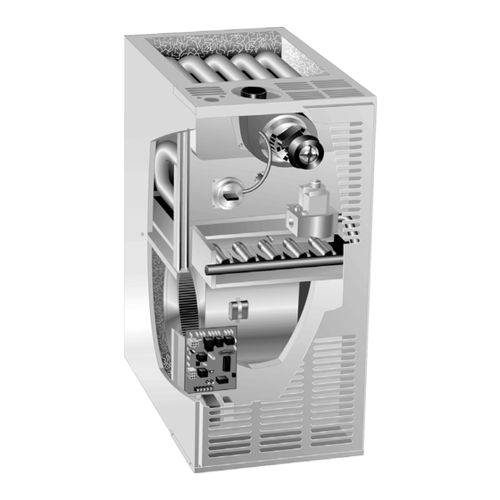
80MGF series units are mid−efficiency gas furnaces
manufactured with tubular heat exchangers formed of alu-
minized or stainless steel. 80MGF units are available in
heating capacities of 45,000 to 140,000 Btuh and cooling
applications up to 5 tons. Refer to Engineering Handbook
for proper sizing.
Units are factory equipped for use with natural gas. A kit is
available for conversion to LPG operation. All 80MGF units
built proir to September 98 use electronic (direct spark) igni-
tion. 80MGF−11 model units are equipped with the Lennox
SureLight ignition system. The 80MGFX unit meets the
California Nitrogen Oxides (NO
Seasonal Efficiency requirements. All units use a redun-
dant gas valve to assure safety shut−off as required by
A.G.A. or C.G.A.
The heat exchanger, burners and manifold assembly can
easily be removed for inspection and service by simply dis-
connecting gas, unplugging wiring harness and spark wires
and removing four screws holding the heat exchanger in
place. Then the heat exchanger slides out of the cabinet.
All specifications in this manual are subject to change.
Procedures outlined in this manual are presented as a rec-
ommendation only and do not supersede or replace local
or state codes. In the absence of local or state codes, the
guidelines and procedures outlined in this manual (except
where noted) are recommended only and do not constitute
code.
Units may be installed in upflow, downflow or horizontal
position. The heat exchanger is designed for upright or
horizontal use only. When the unit is installed in the down-
flow position, the heat exchanger is field removed and re-
installed so it is upright when the cabinet is inverted. No
field conversion is required when the unit is installed in the
horizontal position.
. . . . . . . . . . . . . . . . . . . . . . . .
. . . . . . . . . . . . . . . . . . . . . .
. . . . . . . . . . . . . . . . . . . . . . .
. . . . . . . . . . . . . . . . . .
. . . . . . . . . . . . . . . . . .
. . . . . . . . . . . . . . . . . . . . . . .
80MGF SERIES UNITS
) Standards and California
x
TABLE OF CONTENTS
1
2
5
7
9
19
. . . . . . . . . . . . . . . . . . . . . . . . .
. . . . . . . . . . . . . . . . . . . .
Page 1
80MGF
Corp. 9801−L2
Revised 08−2004
19
. . . . .
20
. . . . . . . . . . . . . . . .
20
. . .
20
. . .
22
24
.
26
.
40
© 1998 Lennox Industries Inc.
Advertisement
Table of Contents

Related Manuals for Lennox 80MGF2-75


Summarization of Contents
Unit Information
80MGF Series Overview
General introduction to the 80MGF series mid-efficiency gas furnaces.
Specifications
Model Specifications Table
Detailed technical specifications for various 80MGF models.
Blower Performance Data
Blower Performance Tables
Air volume data at various speeds for different 80MGF models.
Filter Air Resistance
Table detailing air resistance for cleanable filters at different airflow rates.
Component Identification & Details
Parts Identification Diagram
Visual identification of furnace components and their orientation.
Unit Components & Controls
Description of main unit components and control systems like RAM and EGC.
SureLight Ignition System
Overview of the SureLight ignition system and its features.
Key Component Descriptions
Detailed descriptions of blowers, motors, safety limits, gas valves, and sensors.
Installation, Service & Maintenance
Installation and Start-Up Procedures
Guidelines for unit installation and safe start-up sequences.
Service Checks and Operation
Procedures for checking system performance, gas, and electrical operation.
Maintenance Procedures
Recommended maintenance tasks including cleaning and filter replacement.
Wiring Diagrams & Sequences of Operation
Wiring Diagrams (RAM, EGC, SureLight)
Electrical wiring diagrams for different control systems.
Sequence of Operation (RAM Control)
Operational sequence for furnaces using the RAM control.
Sequence of Operation (EGC Control)
Operational sequences for EGC-1 and EGC-2 controls.
Sequence of Operation (SureLight Control)
Operational sequences for the SureLight ignition control system.
Troubleshooting
Troubleshooting Sequences (Heating, Cooling, Fan)
Flowcharts for diagnosing operational issues in heating, cooling, and fan modes.
EGC Diagnostic Codes
Interpretation of diagnostic LED codes for EGC control failures.
SureLight Control Troubleshooting
Common problems and corrective actions for SureLight control system failures.
Service Notes
General Service Notes
Miscellaneous notes and considerations for service technicians.
Need help?
Do you have a question about the 80MGF2-75 and is the answer not in the manual?
Questions and answers