Table of Contents
Advertisement
Service Literature
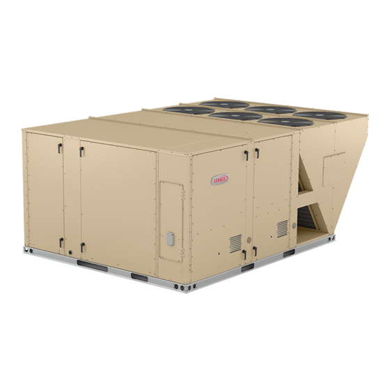
The LCM156H, 180, 210, 240 and 300 units are configure to
order units (CTO) with a wide selection of factory installed
options.
Cooling capacities range from 13 to 25 tons (45.7 to 88 kW).
LCM156 and 180 utilize three compressors and four con
denser fans, while LCM210, 240 and 300 utilize four com
pressors and six condenser fans.
Optional electric heat is factory- or field-installed. Electric
heat operates in single or multiple stages depending on the
kW input size. 15kW to 60 kW heat sections are available
for the LCM156 and 180 units and 15 kW to 90 kW heat sec
tions are available for the LCM210, 240, 300.
Multi-Stage Air Volume MSAV
The VFD-driven blower will operate at lower speeds when
demand is low and increase to higher speeds when demand
is high.
Variable speed VAV system is available as an option which
enables supply duct static measurement to control blower
CFM and discharge air temperature to control cooling
stages.
All LCM units are designed to accept any of several differ
ent energy management thermostat control systems with
minimum field wiring. Factory- or field-provided control op
tions connect to the unit through Smartwiret connectors.
When "plugged in" the controls become an integral part of
the unit wiring.
The CORE Control System is designed to accelerate
equipment install and service. Standard with all Model L™
rooftop units, control system integrates key technologies
that lower installation costs, drive system efficiency, and
protect your investments.
The CORE Unit Controller is a microprocessor-based con
troller that provides flexible control of all unit functions.
Information contained in this manual is intended for use by
qualified service technicians only. All specifications are sub
ject to change. Procedures outlined in this manual are pre
sented as a recommendation only and do not supersede or
replace local or state codes.
If the unit must be lifted for service, rig unit by attaching four
cables to the holes located in the unit base rail (two holes at
each corner). Refer to the installation instructions for the proper
rigging technique.
Revised 08/2021
LCM156U through 300U
®
blower option is
available.
100025
WARNING
Improper installation, adjustment, alteration, service
or maintenance can cause property damage, person
al injury or loss of life. Installation and service must
be performed by a qualified installer or service
agency.
Electric shock hazard. Can cause injury
or death. Before attempting to perform
any service or maintenance, turn the
electrical power to unit OFF at discon
nect switch(es). Unit may have multiple
power supplies.
Table of Contents
. . . . . . . . . . . . . . . . . . . . . . . . . . . .
. . . . . . . . . . . . . . . . . . . . . . . . . . . . .
. . . . . . . . . . . . . . . . . . . . . . . . . . . . . .
. . . . . . . . . . . . . . . . . . . . . . . . . .
. . . . . . . . . . . . . . . . . . . . . . . . . . .
. . . . . . . . . . . . . . . . . . . . . . . . .
Page 1
LCM SERIES
13 to 25 ton
45.7 to 88 kW
WARNING
. . . . . . . . . . . . . . . . . . . . .
. . . . . . . . . . . . . .
. . . . . . . . . . . . . . . . . . .
. . . . . . . . . . . . . . . . . . .
. . . . . . . . . . . . . . . . . . . . . . .
. . . . . . . . . . . . . . . . . . . .
. . . . . . . . . . . . . . . .
. . . . . . . . . . . . . . . . . . . . . .
. . . . . . . . . . . . . . . . . . . . . . .
. . . . . . . . . .
Page 2
Page 6
Page 9
Page 12
Page 17
Page 18
Page 18
Page 33
Page 35
Page 35
Page 35
Page 36
Page 40
Page 44
Page 46
Page 48
Advertisement
Table of Contents

Subscribe to Our Youtube Channel
Related Manuals for Lennox LCM Series


Summary of Contents for Lennox LCM Series
-
Page 1: Table Of Contents
LCM SERIES 13 to 25 ton 100025 45.7 to 88 kW Revised 08/2021 Service Literature LCM156U through 300U The LCM156H, 180, 210, 240 and 300 units are configure to order units (CTO) with a wide selection of factory installed options. -
Page 2: Options / Accessories
Factory Blower Belt Auto-Tensioner Factory CABINET Combination Coil/Hail Guards 13T12 CONTROLS Blower Proving Switch 21Z10 54W27 Commercial LonTalk Module - For Lennox CORE Control System ® ® Controls Novar Factory ® L Connection Building Automation System - - - ®... - Page 3 OPT IONS / A C C ESSORIES Unit Model No Catalog Item Description Number 156 180 210 240 300 INDOOR AIR QUALITY Air Filters 54W67 Healthy Climate High Efficiency Air Filters MERV 8 (Order 6) ® 24 x 24 x 2 in. MERV 13 (Order 6) 52W40 21U42...
- Page 4 OPT IONS / A C C ESSORIES Unit Model No Catalog Item Description Number 156 180 210 240 300 ELECTRIC HEAT 22H66 15 kW 208/230V-3ph 460V-3ph 22H67 30 kW 208/230V-3ph 22H68 460V-3ph 22H69 208/230V-3ph 22H70 460V-3ph 22H71 45 kW 208/230V-3ph 22H72 22H73 460V-3ph...
- Page 5 OPT IONS / A C C ESSORIES Unit Model No Catalog Item Description Number 156 180 210 240 300 ROOF CURBS Hybrid Roof Curbs, Downflow 8 in. height curb 11F58 14 in. height curb 11F59 18 in. height curb 11F60 24 in.
-
Page 6: Specifications
S P EC IFIC ATIONS 1 3 TO N General Data Nominal Tonnage 13 Ton 13 Ton Model Number LCM156U4M LCM156U4V Efficiency Type Ultra-High Ultra-High Blower Type SZVAV (Single Zone (Variable Air Variable Air Volume) Volume) Cooling Gross Cooling Capacity - Btuh 154,000 154,000 Performance... - Page 7 SP ECIF ICATIONS 15 TO N | 1 7 . 5 TO N General Data Nominal Tonnage 15 Ton 15 Ton 17.5 Ton 17.5 Ton Model Number LCM180U4M LCM180U4V LCM210U4M LCM210U4V Efficiency Type Ultra-High Ultra-High Ultra-High Ultra-High Blower Type SZVAV SZVAV (Single Zone (Variable Air...
- Page 8 S PEC IFIC ATIONS 2 0 TO N | 2 5 TO N General Data Nominal Tonnage 20 Ton 20 Ton 25 Ton 25 Ton Model Number LCM240U4M LCM240U4V LCM300U4M LCM300U4V Efficiency Type Ultra-High Ultra-High Ultra-High Ultra-High Blower Type SZVAV SZVAV (Single Zone (Variable Air...
- Page 9 Page 9...
-
Page 10: Blower Data
BLO WER DATA FACTORY INSTALLED BELT DRIVE KIT SPECIFICATIONS Motor Efficiency Nominal Maximum Drive Kit Number RPM Range Standard 2.30 535 - 725 Standard 2.30 710 - 965 Standard 3.45 535 - 725 Standard 3.45 710 - 965 Standard 5.75 685 - 856 Standard 5.75... - Page 11 BLO WER DATA POWER EXHAUST FAN PERFORMANCE Return Air System Static Pressure Air Volume Exhausted in. w.g. 0.00 8630 0.05 8210 0.10 7725 0.15 7110 0.20 6470 0.25 5790 0.30 5060 0.35 4300 0.40 3510 0.45 2690 0.50 1840 CEILING DIFFUSER AIR RESISTANCE - in. w.g. Step-Down Diffuser Flush Diffuser RTD11-185S...
-
Page 12: Electrical / Electric Heat Data
ELECTRIC AL/ELECTRIC H EAT DATA 1 3 TO N Model No. LCM156U4 Voltage - 60Hz 208/230V-3ph 460V-3ph Compressor 1 Rated Load Amps 13.3 Locked Rotor Amps Compressor 2 Rated Load Amps 14.5 Locked Rotor Amps Compressor 3 Rated Load Amps 14.5 Locked Rotor Amps Outdoor Fan... - Page 13 ELECTRIC AL/ELECTRIC H EAT DATA 1 5 TO N Model No. LCM180U4 Voltage - 60Hz 208/230V-3ph 460V-3ph Compressor 1 Rated Load Amps 15.7 Locked Rotor Amps Compressor 2 Rated Load Amps Locked Rotor Amps Compressor 3 Rated Load Amps Locked Rotor Amps Outdoor Fan Full Load Amps Motors (4)
- Page 14 ELECTRIC AL/ELECTRIC H EAT DATA 1 7 .5 TO N Model No. LCM210U4 Voltage - 60Hz 208/230V-3ph 460V-3ph Compressor 1 Rated Load Amps 13.3 Locked Rotor Amps Compressor 2 Rated Load Amps 14.5 Locked Rotor Amps Compressor 3 Rated Load Amps 14.5 Locked Rotor Amps Compressor 4...
- Page 15 ELECTRIC AL/ELECTRIC H EAT DATA 2 0 TO N Model No. LCM240U4 Voltage - 60Hz 208/230V-3ph 460V-3ph Compressor 1 Rated Load Amps 16.8 Locked Rotor Amps Compressor 2 Rated Load Amps 13.2 Locked Rotor Amps Compressor 3 Rated Load Amps 13.2 Locked Rotor Amps Compressor 4...
- Page 16 ELECTRIC AL/ELECTRIC H EAT DATA 2 5 TO N Model No. LCM300U4 Voltage - 60Hz 208/230V-3ph 460V-3ph Compressor 1 Rated Load Amps 16.8 Locked Rotor Amps Compressor 2 Rated Load Amps 19.6 Locked Rotor Amps 66.1 Compressor 3 Rated Load Amps 22.4 10.6 Locked Rotor Amps...
-
Page 17: Electric Heat Capacities
ELECTRIC H EAT CAPACITIES 15 kW 30 kW 45 kW 60 kW 90 kW Volts Btuh No. of Btuh No. of Btuh No. of Btuh No. of Btuh No. of Input Input Output Stages Input Output Stages Input Output Stages Input Output Stages... -
Page 18: Unit Parts Arrangement
PARTS ARRANGEMENT (LCM210, 240, 300 SHOWN) EVAPORATOR REHEAT FILTERS COIL COIL CONDENSER FANS (SIX - 24 X 24 X 2”) (4 ON 156 & 180) BLOWERS ECONOMIZER DAMPERS (OPTIONAL) BLOWER MOTOR BLOWER INVERTER 8.8.8.8 UNIT CONTROLLER CONDENSATE DRAIN CONDENSER COILS VARIABLE SPEED COMPRESSOR INVERTER COMPRESSORS... - Page 19 M4 (A55) K65 K231 A178 K202 K203 F10 K1 K191 K14 K146 (G volt) (G volt) VSC Inverter ELECTRIC HEAT SECTION ELECTRIC HEAT SECTION FIGURE 3 gizes B13 in response to second stage cool demand. In 4-Terminal Block TB13 210, 240 and 300 units K14 and K146 (energized by A178) TB13 terminal block distributes line voltage power to the energize compressors B13 and B20 in response to second line voltage items in the unit.
- Page 20 9-Power Exhaust Relay K65 & K231 (PED 12-Inverter Start Forward Rotation Relay K203 units) (optional) Relay is used in optional Staged-Blower units and is a Power exhaust relays K65 and K231 are N.O. DPDT relays three-pole double-throw relay with a 24VAC coil. K203 is with a 24VAC coil.
- Page 21 VAV Supply Static Sensor The supply duct differential static pressure sensor (A30) is an analog sensor with a 0-10VDC output over a range of 0-5"w.c as shown in the following table. The sensor is powered with 24VAC. Table 4 Static Pressure Pressure "w.c.
- Page 22 LINE VOLTAGE IN TELEMECANIQUE OVERLOAD RELAY TRIP CLEAR INDICATION COVER WINDOW DETAIL SHOWING RESET BUTTON (SHOWN ADJUSTED TO MANUAL POSITION CLOSED) AMP SETTING Lift clear cover and turn adjustment screw STOP POINTER counterclockwise. Reset screw will pop out BUTTON when pointer is in M (manual position). Close (RED) cover to lock reset screw into position.
- Page 23 Compressor Detail LCM156/300 B1, B2, B13 LCM210/300 B20 Sensor ELECTRIC HEAT SECTION ELECTRIC HEAT SECTION FIGURE 6 Page 23...
- Page 24 156, 180 REFRIGERANT CIRCUITS ALL THREE EVAPORATOR COIL CIRCUITS ARE INTERTWINED EVAPORATOR COIL (not to scale) CIRCUIT 1 & 2 CIRCUIT 2 & 3 INTERTWINED CONDENSER COILS CIRUIT 1 INTERTWINED CIRCUIT 3 CONDENSER COIL 210, 240, 300 REFRIGERANT CIRCUITS ALL FOUR EVAPORATOR COIL CIRCUITS ARE INTERTWINED EVAPORATOR COIL...
- Page 25 B-Cooling Components 3-High Pressure Switches S4, S7, S28, S96 S4 all units Model L ultra high efficiency units use independent cooling S7 all units circuits consisting of one compressor, one condenser coil, S28 all units S96 and one evaporator coil per circuit. See figures 7 and 6. 210, 240, 300 Four draw-through type condenser fans are used in The high pressure switches is an auto‐reset SPST N.C.
- Page 26 6-Filter Drier (all units) Supply Air Staged Units and Units Equipped With Op tional Voltage or Phase Detection - The Unit Controller Units have a filter drier located in the liquid line of each refrig checks the incoming power during start-up. If the voltage or erant circuit at the exit of each condenser coil.
- Page 27 B-Blower Access 2. With all access panels in place, measure static pres sure external to unit (from supply to return). Blower per 1. Disconnect jack/plug connector to blower motor. Also formance data is based on static pressure readings disconnect jack/plug connector heating limit switches taken in locations shown in figure 8.
- Page 28 BLOWER ASSEMBLY - NO TENSIONER TO INCREASE CFM LOOSEN ALLEN SCREW & TO INCREASE BELT TENSION TURN PULLEY CLOCKWISE 1-Loosen four screws securing blower motor to TO DECREASE CFM sliding base. TURN PULLEY 2-Turn adjusting screw to the left, or counter COUNTERCLOCKWISE clockwise, to move the motor downward and tighten the belt.
- Page 29 PULLEY ALIGNMENT - WITH TENSIONER FIXED PULLEY ADJUSTABLE PULLEY TENSIONER BOLT AND TENSIONER ADJUSTMENT NUT BOLT ALIGN TENSIONER MARKS FIGURE 12 Blowers Equipped With Belt Tensioner 3. Measure belt deflection force. For a used belt, the de flection force should be 5 lbs. (35kPa) . A new belt de 1.
- Page 30 D- OPTIONAL ELECTRIC HEAT 3-High Temperature Limits S15 and S107 (Primary) See ELECTRICAL / ELECTRIC HEAT DATA and ELEC S15 and S107 are SPST N.C. auto‐reset thermostats located on the back panel of the electric heat section TRIC HEAT CAPACITIES (table of contents) for LCH to below the heating elements.
- Page 31 ELECTRIC HEAT VESTIBULE PARTS ARRANGEMENT TERMINAL STRIP FIRST HEAT SECTION (LEFT SIDE) (TB3) FUSE F3 SECOND STAGE ELECTRIC FUSE F3 HEAT CONTACTOR K16 FIRST STAGE ELECTRIC HEAT CONTACTOR K15 SECOND HEAT SECTION (RIGHT SIDE) TERMINAL STRIP (TB3) FUSE F3 FIRST STAGE ELECTRIC SECOND STAGE ELECTRIC HEAT CONTACTOR K17 HEAT CONTACTOR K18...
- Page 32 EHA 15, 30, 45, 60 and 90 KW ELECTRIC HEAT SECTION PARTS ARRANGEMENT HEATING ELEMENTS HE1 - HE14 ELECTRIC HEAT VESTIBULE CONTROL WIRE HARNESS PRIMARY ELECTRIC HEAT LIMIT S15(1 SECTION) S107(2 SECTION) FIGURE 16 TABLE 6 ELECTRIC HEAT SECTION FUSE RATING FUSE (3 each) EHA QUANTITY VOLTAGES...
-
Page 33: Ii-Charging
II-CHARGING TABLE 8 156 Reheat Compressor 1 Frequency 56Hz - 581015-01 A-Refrigerant Charge and Check - Fin/Tube Circuit 1 Circuit 2 Circuit 3 Outdoor Coil Coil Suct. Suct. Suct. Disch. Disch. Disch. Entering WARNING-Do not exceed nameplate charge under any condition. psig psig psig... - Page 34 TABLE 12 TABLE 16 210 Reheat Compressor 1 Frequency 48Hz - 581019-01 300 Reheat Compressor 1 Frequency 68Hz - 581023-01 Circuit 1 Circuit 2 Circuit 3 Circuit 4 Outdoor Circuit 1 Circuit 2 Circuit 3 Circuit 4 Outdoor Coil En Dis.
-
Page 35: Iii-Startup - Operation
III-STARTUP - OPERATION B-Cooling System Service Checks LCM units are factory charged and require no further adjust Refer to startup directions and to the unit wiring diagram ment; however, charge should be checked periodically using when servicing. See unit nameplate for minimum circuit ampacity and maximum fuse size. -
Page 36: Vi-Accessories
Optional supply/return transitions C1DIFF33C-1 and frames are recommended in all other applications but not C1DIFF34C-1 are available for use with LCM series units required. If the LCM units are not mounted on a flat (roof) utilizing optional C1CURB roof curbs. Transition must be surface, they MUST be supported under all edges and un... - Page 37 E-E1ECON15C-2 Standard and E1ECON17C-1 C1DAMP10 MANUAL OUTDOOR AIR DAMPER High Performance Economizer (Field or Factory Installed) The optional economizer can be used with downflow and horizontal air discharge applications. The economizer uses outdoor air for free cooling when temperature and/or humidity is suitable.
- Page 38 NOTE - All economizer modes of operation will mod H-Optional Cold Weather Kit (Canada only) ulate dampers to 55_F (13_C) supply air. Electric heater is available to automatically control the F-Gravity Exhaust Dampers minimum temperature in the gas burner compartment. Heater is C.G.A.
- Page 39 I-Control Systems M-Optional UVC Lights The A55 Unit Controller provides all control function for the ® The Healthy Climate germicidal light emits ultraviolet rooftop unit. Default operation requires a standard room (UVC) energy that has been proven effective in reducing thermostat or direct digital controller (DDC).
-
Page 40: Vii-Hot Gas Re-Heat
VII-FACTORY-INSTALLED Hot Gas Re-Heat TABLE 18 Relative Humidity (%RH + 3%) Sensor Output (VDC) General 2.00 Hot gas reheat units provide a dehumidifying mode of op 3.00 eration. These units contain a reheat coil adjacent to and downstream of the evaporator coil. Reheat coil solenoid 4.00 valves, L14 and L30, route hot discharge gas from the 5.00... - Page 41 REHEAT MODE REFRIGERANT ROUTING 156, 180 UNITS Note: Two refrigerant circuits are shown; both circuits operate during reheat. EVAPORATOR CIRCUITS 1 & 2 EXPANSION ARE INTERTWINED VALVES CIRCUIT 2 & 3 CONDENSER COILS INTERTWINED REHEAT COIL CIRCUIT 1 CONDENSER COIL CHECK VALVE REHEAT...
- Page 42 REHEAT MODE REFRIGERANT ROUTING 210, 240 AND 300 UNITS Note: Two refrigerant circuits are shown; both circuits operate during reheat. ALL FOUR CONDENSER COIL CONDENSER COIL EVAPORATOR CIRCUIT 2 & 4 ARE EXPANSION CIRCUIT 1 & 3 ARE INTERTWINED COILS ARE VALVES INTERTWINED INTERTWINED...
- Page 43 TABLE 19 REHEAT OPERATION Thermostat Mode With 24V Humidistat Humidity Demands Operation Compressor 1 reheat on Compressor 1 operates at 100% Reheat valve is energized 24V Demand for Dehumidification only Remaining compressors are off Blower and outdoor fans modulate to maintain indoor coil and discharge air temperatures Compressor 1 &...
-
Page 44: Viii-Staged Blower
VIII--Multi-Staged Blower RTU MENU > SETTINGS > RTU OPTIONS > DAMPER Tap "Next" to skip tabs and complete damper position cali A-Design Specifications bration until "Damper Calibration Blower Speed High" tab Use the “Blower CFM Design Specifications” table at appears. tached to the unit (table 18 in the installation instructions) to Measure the intake air CFM. - Page 45 TABLE 20 HEATING, VENTILATION & SMOKE MINIMUM AND MAXIMUM CFM Unit Heating CFM Vent CFM Smoke CFM Model Speed Heat Code Default Default Default LGM156U Low, Std, Med L, S, M 4500 5200 6250 1150 1950 5200 6250 LGM180U Low, Std, Med L, S, M 4500 6000...
-
Page 46: Ix- Vav System
IX--VAV System TABLE 22 RECORD ADJUSTED SETPOINTS Units contain a supply air blower equipped with a variable Setpoint Setpoint Display Parameter frequency drive A96 (VFD) which varies supply air CFM. Description “w.c. Setting The supply air VFD (A96) is located in the control area. See Smoke figure 26. - Page 47 B-Unit Operation 12. Restore power to unit. Blower will operate in constant air volume (CAV) mode. Use the mobile app to check unit mechanical operation. See the Service - Test section of the Unit Controller manual. Note - The indoor blower motor will start as soon as the main unit power is restored.
-
Page 48: X-Wiring And Operation Sequence
X-Wiring Diagrams and Sequence of Operation Economizer MS7110K RANGE 2−10 VDC 538072−01 NF24−SR AF24−SR RANGE 2−10 VDC P104 P105 RT16 J104 J105 P384 J384 MAIN CTRL Model: LCM, LGM Series RTU HTG CLG ACCS ACCS Economizer & Motorized OAD WIRING DIAGRAM FLOW Voltage: All Voltages Supersedes: N/A... - Page 49 THERMOSTAT 538078− 0 1 A173 CTRL SMOKE DETECT J250 P250 P251 J251 J252 P252 P253 J253 FIRE ALARM CONTACT SUPPLIED BY OTHERS FROM IAQ WIRING DIAGRAM DI−1 P299 P387 J299 J387 MAIN CTRL J297 J298 P297 P298 J387 J298 J297 J299 IAQ+ IAQ+ BACNET GATEWAY...
- Page 50 EHA15/90 Y Voltage JACK/PLUG DESCRIPTION FUSE, ELECTRIC HEAT 5 ELECTRIC HEAT CONTROL CONTROL, BOARD LENNOX FUSE, ELECTRIC HEAT 6 ELECTRIC HEAT CONTROL BOARD, COMP 3 & 4, C3 2nd STAGE HEAT A178 FUSE, ELECTRIC HEAT 7 FUSE, ELECTRIC HEAT FUSE, ELECTRIC HEAT 8 FUSE, UNIT FUSE, UNIT −...
- Page 51 EHA-15/90 G Voltage Page 51...
- Page 52 SEQUENCE OF OPERATION EHA-15, 30, 45, 60, 90 - Y & G The Y voltage diagram use elements configured in N.O. contacts K17‐1 close allowing the first set of a Wye. The G and J voltage diagram use elements elements in heat section two (right side) to be en configured in a Delta.
- Page 53 Sequence of Operation LGM/LCM156 & 180U 1 - Line voltage from TB13 energizes transformer T1 and T18. Transformer T1 and T18 provides 24VAC power to the main controller A55. The transformers also provide 24VAC power to the unit cooling, heating and blower controls and thermostat ECONOMIZER OPERATION 2- The A55 Unit Controller receives a demand and energizes exhaust fan relay K65 and K231 with 24VAC at 50% (travel) outside air damper open (adjustable).
- Page 54 LGM/LCM156U/180U Y Voltage With By-Pass Page 54...
- Page 55 LGM/LCM156U/180U G Voltage With By-Pass Page 55...
- Page 56 LGM/LCM156U/180U Y Voltage With No By-Pass Page 56...
- Page 57 LGM/LCM156U/180U G Voltage With No By-Pass Page 57...
- Page 58 Sequence of Operation LGM/LCM210, 240U, 300U 1- Line voltage from TB13 energizes transformer T1 and T18. Transformer T1 and T18 provides 24VAC power to the main controller A55. The transformers also provide 24VAC power to the unit cooling, heating and blow er controls and thermostat.
- Page 59 LGM/LCM210U, 240U, 300U Y Voltage With No By-Pass Page 59...
- Page 60 LGM/LCM210U, 240U, 300U G Voltage With No By-Pass Page 60...
- Page 61 LGM/LCM210U, 240U, 300U Y Voltage With By-Pass Page 61...
- Page 62 LGM/LCM210U, 240U, 300U G Voltage With By-Pass Page 62...
Need help?
Do you have a question about the LCM Series and is the answer not in the manual?
Questions and answers