Table of Contents
Advertisement
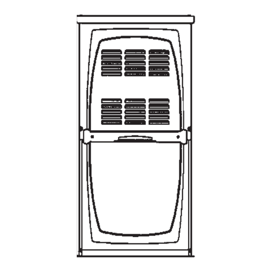
Upflow / Horizontal Left and Right Air Discharge
This is a safety alert symbol and should never be ignored. When you see this symbol on labels or in
manuals, be alert to the potential for personal injury or death.
As with any mechanical equipment, personal injury can
result from contact with sharp sheet metal edges. Be
careful when you handle this equipment.
Unit Dimensions ............................................................ 2
A80UH1E & 80G1UHE
Shipping and Packing List ............................................ 4
Safety Information ......................................................... 4
Use of Furnace as a Construction Heater .................... 5
General ......................................................................... 6
Combustion, Dilution, Ventilation Air ............................. 6
Setting Equipment ........................................................ 9
Filters .......................................................................... 12
Duct System ................................................................ 12
Venting ........................................................................ 13
Gas Piping .................................................................. 23
*P506842-01*
(P) 506842-01
506842-01
INSTALLATION INSTRUCTIONS
A80UH1E & 80G1UHE
Warm Air Gas Furnace
This manual must be left with the homeowner for future reference.
CAUTION
TABLE OF CONTENTS
Parts Arrangement .............. 3
Gas Furnace ........................ 4
Improper installation, adjustment, alteration, service or
maintenance can cause property damage, personal injury
or loss of life. Installation and service must be performed
by a licensed professional installer (or equivalent), service
agency or the gas supplier.
Electrical ..................................................................... 25
Unit Start-Up ............................................................... 29
Heating Sequence of Operation ................................. 30
Gas Pressure Adjustment ........................................... 30
High Altitude ................................................................ 31
Other Unit Adjustments ............................................... 31
Blower Motor Performance ......................................... 33
Service ........................................................................ 35
Planned Service .......................................................... 38
Integrated Control Diagnostic Codes .......................... 38
Repair Parts List ......................................................... 39
Start-Up Check List ..................................................... 40
A Lennox International, Inc. Company
Issue 1132
WARNING
Manufactured By
Allied Air Enterprises, Inc.
215 Metropolitan Drive
West Columbia, SC 29170
Page 1 of 42
Advertisement
Table of Contents

Related Manuals for Lennox A80UH1E


Summary of Contents for Lennox A80UH1E
-
Page 1: Table Of Contents
Start-Up Check List ............. 40 Venting ................ 13 Gas Piping ..............23 Manufactured By *P506842-01* Allied Air Enterprises, Inc. A Lennox International, Inc. Company 215 Metropolitan Drive (P) 506842-01 West Columbia, SC 29170 506842-01 Issue 1132 Page 1 of 42... -
Page 2: Unit Dimensions
A80UH1E & 80G1UHE Unit Dimensions - inches (mm) NOTE - 20C and 20D size units installed in upflow applications that require air volumes of 1800 cfm (850 L/s or greater must have one of the following: 1. Single side return air with transition, to accommodate 20 x 25 x 1 in. - Page 3 Expanded View Figure 1 506842-01 Issue 1132 Page 3 of 42...
-
Page 4: A80Uh1E & 80G1Uhe Gas Furnace
A80UH1E & 80G1UHE Gas Furnace The A80UH1E & 80G1UHE gas furnace is shipped ready CAUTION for installation in the upflow or horizontal right position (for horizontal left position the combustion air pressure switch As with any mechanical equipment, personal injury can must be moved). -
Page 5: Use Of Furnace As A Construction Heater
Temperature Rise This furnace may be installed in alcoves, closets, attics, basements, garages, and utility rooms in the upflow or NOTE: Furnace must be adjusted to obtain a temperature horizontal position. rise within the range specified on the unit nameplate. Failure to do so may cause erratic limit operation and may result in This furnace design has not been CSA certified for premature heat exchanger failure. -
Page 6: General
General Combustion, Dilution & Ventilation Air In the past, there was no problem in bringing in sufficient These instructions are intended as a general guide and do outdoor air for combustion. Infiltration provided all the air not supersede local codes in any way. Consult authorities that was needed. - Page 7 All gas fired appliances require air for the combustion Equipment in Confined Space - All Air From Inside process. If sufficient combustion air is not available, the furnace or other appliances will operate inefficiently and unsafely. Enough air must be provided to meet the needs of all fuel burning appliances and appliances such as exhaust fans which force air out of the house.
- Page 8 When ducts are used, they shall be of the same cross EQUIPMENT IN CONFINED SPACE sectional area as the free area of the openings to which (ALL AIR FROM OUTSIDE) they connect. The minimum dimension of rectangular air ducts shall be no less than 3 inches (75 mm). In calculating free area, the blocking effect of louvers, grilles, or screens must be considered.
-
Page 9: Setting Equipment
Setting Equipment Upflow Applications Allow for clearances to combustible materials as indicated WARNING on the unit nameplate. Minimum clearances for closet or alcove installations are shown in Figure 8. Do not install the furnace on its front or its back. Do not connect the return air ducts to the back of the furnace. - Page 10 Return Air - Upflow Applications Return air can be brought in through the bottom or either Single Side Return Air side of the furnace installed in an upflow application. If the (with transition and filter) furnace is installed on a platform with bottom return, make an airtight seal between the bottom of the furnace and the platform to ensure that the furnace operates properly and safely.
- Page 11 Removing the Bottom Panel Horizontal Applications The furnace can be installed in horizontal applications. Order Remove the two screws that secure the bottom cap to the horizontal suspension kit (51W10) from Allied Air, or use furnace. Pivot the bottom cap down to release the bottom equivalent suspension method.
-
Page 12: Filters
Horizontal Application Unit installed on Platform Table 1 Duct System Use industry approved standards (such as those published by Air Conditioning Contractors of America or American Society of Heating, Refrigerating and Air Conditioning Engineers) to size and install the supply and return air duct Figure 14 system. -
Page 13: Venting
Venting 1. Remove the four mounting screws (Figure 15) which A 4 inch diameter flue transition is factory installed on the secure the combustion air inducer / pressure switch combustion air inducer outlet of all models. Figure 16 shows assembly to the orifice plate. Lift the assembly and rotate the combustion air inducer as shipped from the factory. - Page 14 HORIZONTAL LEFT POSITION HORIZONTAL RIGHT POSITION Top Vent discharge Top Vent Discharge • Disconnect pressure switch hose from barbed fitting on the pressure switch assembly. Remove pressure switch assembly (1 screw) and cut • Gas supply piping must be brought into the unit from the bottom in order wire tie to free pressure switch wires.
- Page 15 These series units are classified as fan assisted Category I Use self drilling sheet metal screws or a mechanical fastener furnaces when vertically vented according to the latest edition to firmly secure the vent pipe to the round collar of the flue of National Fuel Gas Code (NFPA 54 / ANSI Z223.1) in the transition.
- Page 16 Common Venting Using Tile Lined Interior Masonry Chimney and Combined Vent Connector NOTE: Refer to provided venting tables for installations. NOTE: The chimney must be properly sized per provided venting tables or lined with listed metal lining system. Figure 25 DO NOT insulate the space between the liner and the Do not install a manual damper, barometric draft regulator, chimney wall with puffed mica or any other loose granular...
- Page 17 5. Multiple appliance vents - The flow area of the largest 13. When the vent connector used for Category I appliances section of vertical vent or chimney shall not exceed 7 must be located in or pass through a crawl space, attic times the smallest listed appliance categorized vent or other areas which may be cold, that portion of the area, drafthood outlet area or flue collar area unless...
- Page 18 Capacity of Type B Double Wall Vents with Type B Double Wall Connectors Serving a Single Category I Appliance NOTE: Single appliance venting configureations with zero lateral lengths are assumed to have no elbows in the vent system. For all other vent configurations, the vent system is assumed to have two 90 °...
- Page 19 Capacity of Type B Double Wall Vents with Single Wall Metal Connectors Serving a Single Category I Appliance NOTE: Single appliance venting configureations with zero lateral lengths are assumed to have no elbows in the vent system. For all other vent configurations, the vent system is assumed to have two 90 °...
- Page 20 Vent Connector Capacity Type B Double Wall Vents with Type B Double Wall Connectors Serving Two or More Category I Appliances Table 5 Common Vent Capacity Type B Double Wall Vents with Type B Double Wall Connectors Serving Two or More Category I Appliances Table 6 Page 20 of 42 Issue 1132...
- Page 21 Vent Connector Capacity Type B Double Wall Vents with Single Wall Metal Connectors Serving Two or More Category I Appliances NOTE: Single appliance venting configureations with zero lateral lengths are assumed to have no elbows in the vent system. For all other vent configurations, the vent system is assumed to have two 90 °...
- Page 22 Removal of the Furnace from Common Vent 3. Close all building doors and windows and all doors In the event that an existing furnace is removed from a between the space in which the appliances remaining venting system commonly run with separate gas appliances, connected to the common venting system are located the venting system is likely to be too large to properly vent and other spaces of the building.
-
Page 23: Gas Piping
Gas Piping 4. The piping should be sloped 1/4 inch (6.4 mm) per 15 feet (4.57 m) upward toward the meter from the furnace. The piping must be supported at proper intervals [every CAUTION 8 to 10 feet (2.44 to 3.01 m)] with suitable hangers or straps. - Page 24 NOTE: BLACK IRON PIPE ONLY TO BE ROUTED INSIDE OF CABINET Figure 26 Horizontal Applications Possible Gas Piping Configurations NOTE: BLACK IRON PIPE ONLY TO BE ROUTED INSIDE OF CABINET Figure 27 Page 24 of 42 Issue 1132 506842-01...
-
Page 25: Electrical
Leak Check The unit is equipped with a field make-up box on the left After gas piping is completed, carefully check all piping hand side of the cabinet. The make-up box may be moved connections (factory and field installed) for gas leaks. Use to the right side of the furnace to facilitate installation. - Page 26 Before connecting the thermostat, check to make sure the Generator Use - Voltage Requirements wires will be long enough for servicing at a later date. Make The following requirements must be kept in mind when sure that thermostat wire is long enough to facilitate future specifying a generator for use with this equipment: removal of blower for service.
- Page 27 Wiring Diagram A80UH1E & 80G1UHE Figure 32 506842-01 Issue 1132 Page 27 of 42...
- Page 28 Typical Field Wiring Diagram Figure 33 Integrated Control (Automatic Hot Surface Ignition System) Figure 34 Page 28 of 42 Issue 1132 506842-01...
-
Page 29: Unit Start-Up
Unit Start-UP 6. Move switch on gas valve to OFF. Do not force. See Figure 35. FOR YOUR SAFETY READ BEFORE LIGHTING UNIT. 7. Wait five minutes to clear out any gas. If you then smell gas, STOP! Immediately call your gas supplier from a neighbor’s phone. -
Page 30: Heating Sequence Of Operation
Heating Sequence Of Operation (Figure 36) NOTE: To obtain accurate reading, shut off all other gas 1. When thermostat calls for heat, combustion air blower appliances connected to meter. starts. 2. Combustion air pressure switch proves blower operation. Supply Pressure Measurement Switch is factory set and requires no adjustment. -
Page 31: High Altitude
High Altitude Units may require manifold pressure adjustment at altitudes IMPORTANT above 2000 ft. In some cases, it is necessary to change the pressure switch to ensure proper combustion. In all cases For Safety, shut unit off and remove manometer as soon (natural gas and LP/propane gas), maximum line pressure as an accurate reading has been obtained. - Page 32 Fan Control NOTE: Do not secure the electrical conduit directly to the The fan on time of 45 seconds is not adjustable. The heat air ducts or structure. fan off delay (amount of time that the blower operates after the heat demand has been satisfied) may be adjusted by Electrical changing the jumper position across the five pins on the 1.
-
Page 33: Blower Motor Performance
Blower Data A80UH1E & 80G1UHE A80UH1E / 80G1UHE 045*12A PERFORMANCE (Less Filter) Air Volume / Watts at Various Blower Speeds Air Volume / Watts at Various Blower Speeds External External Medium- Medium- Medium- Medium- Static Static High High Medium Medium... - Page 34 Blower Data A80UH1E & 80G1UHE A80UH1E / 80G1UHE 090*16C PERFORMANCE (Less Filter) Air Volume / Watts at Different Blower Speeds Single Side Return Air Air volumes in bold require field Bottom Return Air, Side Return Air with Optional Return External fabricated transition to accommondate 20 x 25 x 1 in.
-
Page 35: Service
Service WARNING WARNING The blower access panel must be securely in place when the blower and burners are operating. Gas fumes, which ELECTRICAL SHOCK, FIRE, could contain carbon monoxide, can be drawn into living OR EXPLOSION HAZARD. space resulting in personal injury or death. Failure to follow safety warnings exactly could result in dangerous operation, serious injury, death or property damage. - Page 36 Cleaning the Heat Exchanger and Burners 5. Remove the collector box located behind the combustion NOTE: Use papers or protective covering in front of the air inducer. Be careful with the collector box gasket. If furnace during cleaning. the gasket is damaged, it must be replaced to prevent 1.
- Page 37 9. Remove screws from both sides, top and bottom of vestibule panel. Remove 5 Screws If Necessary 10. Remove heat exchanger. It may be necessary to spread (either side of cabinet) cabinet side to allow more room. If so, remove five screws from the left side or right side of cabinet.
-
Page 38: Planned Service
PLANNED SERVICE FAILURE CODES The following items should be checked during an annual inspection. Power to the unit must be shut off for the service technician’s safety. Fresh air grilles and louvers (on the unit and in the room where the furnace is installed) - Must be open and unobstructed to provide combustion air. -
Page 39: Repair Parts List
REPAIR PARTS LIST The following repair parts are available through independent Allied Air dealers. When ordering parts, include the complete furnace model number listed on the CSA International nameplate — Example: A801UH045JP24A-01. All service must be performed by a licensed professional installer (or equivalent), service agency, or gas supplier. Heating Parts Cabinet Parts Flame sensor... -
Page 40: Start-Up Check List
START-UP & PERFORMANCE CHECK LIST UNIT SET UP Page 40 of 42 Issue 1132 506842-01... - Page 41 UNIT OPERATION 506842-01 Issue 1132 Page 41 of 42...
- Page 42 REQUIREMENTS for COMMONWEALTH of MASSACHUSETTS Modifications to NFPA-54, Chapter 10 - 4. INSPECTION. The state or local gas inspector of the Revise NFPA-54 section 10.8.3 to add the following side wall, horizontally vented, gas-fueled equipment shall requirements: not approve the installation unless, upon inspection, the For all side wall, horizontally vented, gas fueled equipment inspector observes carbon monoxide detectors and installed in every dwelling, building or structure used in whole...
Need help?
Do you have a question about the A80UH1E and is the answer not in the manual?
Questions and answers