Advertisement
Table of Contents
- 1 Table of Contents
- 2 Introduction
- 3 Specifications
- 4 Blower Data
- 5 Parts Identification
- 6 I Unit Components
- 7 Installation
- 8 Start up
- 9 Preliminary Seasonal Checks
- 10 Heating Start up
- 11 Heating System Service Checks
- 12 Typical Operating Characteristics
- 13 Maintenance
- 14 Wiring and Sequence of Operation
- 15 Surelight Control Troubleshooting
- Download this manual
Service Literature
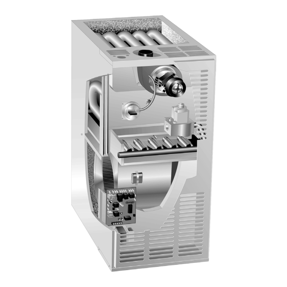
80MGF series units are mid−efficiency gas furnaces
manufactured with tubular heat exchangers formed of alu-
minized or stainless steel. 80MGF units are available in
heating capacities of 45,000 to 140,000 Btuh and cooling
applications up to 5 tons. Refer to Engineering Handbook
for proper sizing.
Units are factory equipped for use with natural gas. A kit is
available for conversion to LPG operation. All 80MGF units
built proir to September 98 use electronic (direct spark) igni-
tion. 80MGF−11 model units are equipped with the Lennox
SureLight ignition system. The 80MGFX unit meets the
California Nitrogen Oxides (NO
Seasonal Efficiency requirements. All units use a redun-
dant gas valve to assure safety shut−off as required by
A.G.A. or C.G.A.
The heat exchanger, burners and manifold assembly can
easily be removed for inspection and service by simply dis-
connecting gas, unplugging wiring harness and spark wires
and removing four screws holding the heat exchanger in
place. Then the heat exchanger slides out of the cabinet.
All specifications in this manual are subject to change.
Procedures outlined in this manual are presented as a rec-
ommendation only and do not supersede or replace local
or state codes. In the absence of local or state codes, the
guidelines and procedures outlined in this manual (except
where noted) are recommended only and do not constitute
code.
Units may be installed in upflow, downflow or horizontal
position. The heat exchanger is designed for upright or
horizontal use only. When the unit is installed in the down-
flow position, the heat exchanger is field removed and re-
installed so it is upright when the cabinet is inverted. No
field conversion is required when the unit is installed in the
horizontal position.
. . . . . . . . . . . . . . . . . . . . . . . .
. . . . . . . . . . . . . . . . . . . . . .
. . . . . . . . . . . . . . . . . . . . . . .
. . . . . . . . . . . . . . . . . .
. . . . . . . . . . . . . . . . . .
. . . . . . . . . . . . . . . . . . . . . . .
80MGF SERIES UNITS
) Standards and California
x
TABLE OF CONTENTS
1
2
5
7
9
19
. . . . . . . . . . . . . . . . . . . . . . . . .
. . . . . . . . . . . . . . . . . . . .
Page 1
80MGF
Corp. 9801−L2
Revised 08−2004
19
. . . . .
20
. . . . . . . . . . . . . . . .
20
. . .
20
. . .
22
24
.
26
.
40
© 1998 Lennox Industries Inc.
Advertisement
Table of Contents

Related Manuals for Lennox 80MGF3/4-100


Summarization of Contents
SPECIFICATIONS AND PERFORMANCE DATA
Optional Accessories
Lists optional accessories available for purchase.
Blower Performance and Filter Resistance
Details air volume at various speeds and filter resistance.
PARTS IDENTIFICATION AND ORIENTATION
Key Components and Systems
Identifies major components like heating parts, burners, blower door, and controls.
UNIT COMPONENTS AND CONTROLS
Blower Door Components
Details electrical components on the blower access door.
Control Systems and Diagnostics
Explains control systems, timings, and diagnostic LEDs.
EGC AND SURELIGHT IGNITION SYSTEMS
EGC Control System
Explains EGC ignition, blower operation, timings, and diagnostics.
SureLight Ignition System
Details the SureLight ignition system, components, and ESD precautions.
TROUBLESHOOTING AND DIAGNOSTIC CODES
EGC Diagnostic Codes
Lists diagnostic codes for the EGC control board.
SYSTEM COMPONENTS AND CHARACTERISTICS
Component Details
Covers blower motors, air blowers, limit controls, sensors, and gas valve.
Operating Characteristics
Discusses operating characteristics like altitude derate and blower adjustment.
INSTALLATION AND START-UP
Start-Up Procedures
Provides instructions for the initial start-up procedure.
HEATING SYSTEM SERVICE CHECKS
Checks, Start-Up, and Shutdowns
Outlines preliminary checks, start-up, safety, and shutdown procedures.
GAS FLOW AND PRESSURE TESTING
Gas Pressure and Flow Adjustments
Guides for testing gas supply pressure and manifold flow.
VI-MAINTENANCE AND CHECKS
Filters, Cleaning, and Blower Maintenance
Guidelines for filters, cleaning, and blower maintenance.
Flue, Chimney, and Electrical Checks
Procedures for checking flue, chimney, and electrical systems.
VII-WIRING AND SEQUENCE OF OPERATION
RAM Control Operation
Explains the sequence of operation for RAM control units.
HEATING SEQUENCE TROUBLESHOOTING
Normal and Abnormal Heating Modes
Step-by-step troubleshooting for heating modes.
COOLING AND FAN ONLY SEQUENCE TROUBLESHOOTING
Cooling and Fan Only Sequences
Troubleshooting sequences for cooling and fan-only operations.
EGC-2 HEATING SEQUENCE OF OPERATION
Normal and Abnormal Heating Modes
Heating sequences for EGC-2 control in normal and abnormal modes.
EGC-2 COOLING AND FAN SEQUENCE OF OPERATION
Cooling and Continuous Fan Sequences
Cooling and continuous fan sequences for EGC-2 control.
EGC-1 HEATING SEQUENCE OF OPERATION
Normal and Abnormal Heating Modes
Heating sequences for EGC-1 control in normal and abnormal modes.
EGC-1 COOLING AND FAN SEQUENCE OF OPERATION
Cooling and Continuous Fan Sequences
Cooling and continuous fan sequences for EGC-1 control.
SURELIGHT HEATING SEQUENCE OF OPERATION
Normal and Abnormal Heating Modes
Heating sequences for SureLight control in normal and abnormal modes.
SURELIGHT COOLING SEQUENCE OF OPERATION
Normal and Abnormal Cooling Modes
Cooling sequences for SureLight control in normal and abnormal modes.
VIII-TROUBLESHOOTING
Problem 1-3: Unit Fails to Operate or Fire
Troubleshooting unit failures related to operation, firing, and blower.
Problem 4-6: Ignition and Burner Issues
Troubleshooting ignition and burner startup/shutdown problems.
Problem 7-8: Control and Blower Signal Issues
Troubleshooting flame sense signals and indoor blower failures.
Need help?
Do you have a question about the 80MGF3/4-100 and is the answer not in the manual?
Questions and answers