Table of Contents
Advertisement
Quick Links
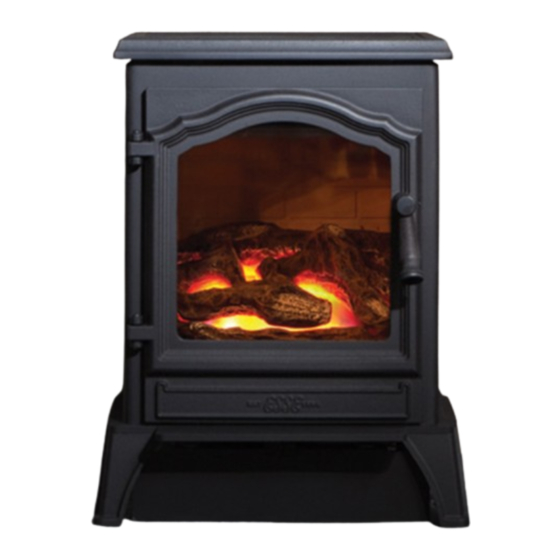
FG500 VISTA/FG525
MANUAL & REMOTE CONTROL FLUELESS GAS FIRED
LOG EFFECT STOVE
INSTALLATION,USER & SERVICING INSTRUCTIONS
(TO BE LEFT WITH THE CUSTOMER)
UK & IRELAND
FG500 VISTA-LR/FG525-LR
For use in UK & Ireland on Natural gas at a supply pressure of 20mbar or
Propane at a supply pressure of 37mbar
GB
IE
Advertisement
Chapters
Table of Contents

Related Manuals for Esse FG525


Summary of Contents for Esse FG525
- Page 1 FG500 VISTA/FG525 MANUAL & REMOTE CONTROL FLUELESS GAS FIRED LOG EFFECT STOVE INSTALLATION,USER & SERVICING INSTRUCTIONS (TO BE LEFT WITH THE CUSTOMER) UK & IRELAND FG500 VISTA-LR/FG525-LR For use in UK & Ireland on Natural gas at a supply pressure of 20mbar or...
-
Page 2: Table Of Contents
INSTALLATION INSTRUCTIONS CONTENTS Important Notes Page 2 Commissioning the Stove Page 12 Technical Information Page 4 Check for Spillage Page 12 Dimensions and Clearances Page 5 Customer Briefing Page 13 Installation Page 7 IMPORTANT NOTES This is a High Efficiency, Flueless Catalytic, and live Fuel Effect Stove. It provides radiant and convected warmth both efficiently and safely utilising the latest type catalytic convector burner technology. - Page 3 The stove must be installed by a competent person in accordance with Gas Safety (Installation and Use) Regulations 1998 or rules in force. It is strongly recommended that a GAS SAFE registered engineer is used for this purpose, as they are the only persons approved by the HSE under the above regulations.
-
Page 4: Technical Information
TECHNICAL INFORMATION Natural Gas Settings FG500-Vista/FG525 GATEGORY HEAT INPUT (NETT) 2.97kW/1.44kW HIGH/LOW SUPPLY PRESSURE 20 mbar INJECTOR SIZE 82/200 GAS CONNECTION 8mm O.D. Tube NOX CLASS EFFICIENCY CLASS COUNTRIES OF CH, CZ, ES, FI, GB, DESTINATION IE, IT, PT & SE OXYPILOT SEAGAS P546 LPG Settings... -
Page 5: Dimensions And Clearances
DIMENSIONS AND CLEARANCES Fig 1a – FG500-Vista Log Dimensions Page 5 FG500V-FG525-REM-I07-010317... - Page 6 Fig 1c – FG525 Log Dimensions Page 6 FG500V-FG525-REM-I07-010317...
-
Page 7: Installation
INSTALLATION Install the stove in accordance with the requirements given below. If a concealed gas connection is to be made prepare the pipe work prior to installing the stove. This stove must be installed on a non-combustible hearth and be of sufficient size to accommodate the stove. - Page 8 Clearances to Non-Combustibles Non-combustible surfaces are defined as brick, metal, marble, concrete etc., and also a number of manmade materials impervious to flame. If in doubt, refer to the material manufacturer for further information before proceeding with installation. Clearances to the sides of the stove is 50mm, however clear and easy access to the controls located on the lower right hand side of the stove must be allowed for, and we would therefore recommend that at least 100mm be allowed.
- Page 9 The shelf depth may be greater than 150mm up to a maximum of 457mm but the height must also be increased accordingly. An increase in height of 25mm is required for every 12.5mm of additional shelf depth. For shelves that are too low, protective devices can be used such as metal heat deflectors, but it must be assured that the shelf does not reach an unacceptable temperature before relying on such a solution.
- Page 10 If a concealed gas connection is to be made, the supply pipe should always be sleeved through walls and floors using the shortest possible route. TTB (Thermocouple interrupter) Fig. 2 Shows the TTB connection on the back of the gas valve. Page 10 FG500V-FG525-REM-I07-010317...
- Page 11 Positioning the Logs Slacken the screw securing the door handle and open the stove door. Position the log on top of the backboard and front log as shown Close the stove door. Tighten the door locking screw. Fig. 3 Backboard Front Log Fig.
-
Page 12: Commissioning The Stove
Under no circumstances should the stove be operated with the door open, without the door attached or the glass in the door damaged, broken or missing COMMISSIONING THE STOVE Once the fire is in place, connected, flued correctly, and the logs are in place, you can proceed with lighting the stove and ensuring the all the features are working correctly. -
Page 13: Customer Briefing
Stress that no extra logs must be added over and above those supplied with the appliance and that any replacements must only be authorized Esse spares. Recommend that the stove is regularly serviced and the flue system checked by qualified persons. -
Page 14: General Notes
USER INSTRUCTIONS CONTENTS General Notes Page 14 Spillage Monitoring System Page 28 Important Notes Page 14 Error Codes Page 28 Positioning the Logs Page 15 Cleaning Page 32 Stove Controls Page 17 Servicing Page 32 Operating The Stove Page 20 Guarantee Page 35 GENERAL NOTES... -
Page 15: Positioning The Logs
When starting the fire the burner usually take around 1 to 10 seconds to ignite and adjust to the maximum power setting. This can take longer on the first lighting as it has to clear out any air locks, also if it is an LPG burner and has been stood unused for time, the gas could have settled in the pipework and again this could take longer. - Page 16 Fig. 7 Log Cluster Fig. 8 Page 16 FG500V-FG525-REM-I07-010317...
-
Page 17: Stove Controls
STOVE CONTROLS This stove is fitted with a gas valve which can be operated via the control unit located behind the right hand foot of the stove, or using the remote control if supplied. Fig 9 - Control unit Page 17 FG500V-FG525-REM-I07-010317... - Page 18 Red indicator LED: OFF: Burner is in standby and ready for start, or already in continuous operation Fast flashing: Control unit is busy and will not accept commands. Medium fast flashing: Control unit is preparing a (re)start of the burner. Slow flashing: Control unit is detecting an error.
- Page 19 Fig 10 – Remote Control Handset Grasp around the handset covering the back and sides to unlock its functions. The green unlock light will illuminate to show when the handset is unlocked and ready to accept commands. (N.B. Keep a grip of handset to keep it unlocked, to continue to operate the command buttons).
-
Page 20: Operating The Stove
OPERATING THE STOVE Quick start user instructions Manual control unit The control unit is situated on your fire. Figure 9 shows the main features of the control. The control requires 3 AA size alkaline batteries to be inserted under the battery compartment cover. - Page 21 When the word “pilot” appears at the bottom left hand corner of the display, immediately release the power button. A second flash of the unlock light and a longer beep will also sound at the time to release the power button. The Fire should be lit within a few seconds.
- Page 22 Detailed remote instructions Setting the Remote control handset Upon successful insertion of the batteries in the Handset the display will be as shown right. The handset will be supplied paired to the fire and all that is required is to set the time of day and select if a 24h hour clock or 12 hour clock display is required and if temperature display is on Celsius or Fahrenheit.
- Page 23 Setting the day of the week Press and release the + and – buttons until the correct day of the week is shown on the display. (Mo = Monday, Tu = Tuesday, We = Wednesday, Th = Thursday, Fr = Friday, Sa=Saturday and Su=Sunday). Press “SET”...
- Page 24 Setting the temperature display to Celsius or Fahrenheit. Press and release the + or - button to toggle between °C and °F. When the display shows the desired symbol, press and release the SET button to store the setting. As the important settings above have now been done. Press and hold (not releasing straight away) the “SET”...
- Page 25 The flashing and sound will last for 60 seconds each time the handset is paged as described. If not found in 60 seconds, page again and so on. NOTE: PRESS “+” Button ONLY, NOT + and - Together as you will accidentally break the handset pairing and have to reset handset to factory state and pair again (seethe pairing handset section if this happens).
- Page 26 The handset is paired originally in the factory follow instructions over leaf only if handset is unpaired or replaced Pairing the handset to the Fire control unit With 2 good quality AA alkaline batteries in the handset in the direction shown inside, if the handset can be paired with a control, it will have the display with the word TESC on the display as shown over leaf.
- Page 27 pairing made and a factory reset of the handset will need to be performed See Factory Reset of display handset Thermostatic Mode Thermostatic mode will allow you to set a desired temperature for the stove to maintain. Once the temperature is reached the fire will reduce the power to minimum and regulate itself to maintain the temperature.
-
Page 28: Spillage Monitoring System
SPILLAGE MONITORING SYSTEM The stove is fitted with a spillage monitoring system which senses any excess temperature due to a flue restriction or blockage. In this event the gas supply is automatically turned off. Should this occur then slide the Fire control unit isolator switch to OFF (0) position and wait approximately 10 minutes for the switch to automatically reset. - Page 29 Page 29 FG500V-FG525-REM-I07-010317...
- Page 30 Page 30 FG500V-FG525-REM-I07-010317...
- Page 31 Page 31 FG500V-FG525-REM-I07-010317...
-
Page 32: Cleaning
CLEANING Ensure that the stove is turned off before cleaning and is cold. DO NOT use abrasive cleaning agents. The stove is supplied with ceramic coals that should only be cleaned and arranged by a qualified person in accordance with the Installation Instructions. SERVICING It is essential that the stove is regularly serviced, and the flue system checked by a qualified person. - Page 33 10. With the stove cold remove the grill and the combustion test plug (Fig.11a/b). Light the stove on HIGH and after 15 minutes check the combustion performance is in accordance with (Fig.12) 11. If the CO figures are more than given in (Fig.12) are below this suggests that either the aeration holes on the burner require cleaning or the ceramic fuel bed components are incorrectly placed.
- Page 34 Fig 11b 525 Series CATALYSER COMBUSTION TEST PLUG SECURING SCREWS Fig 12. Above Catalyser Below Catalyser CO ppm Less than 10 Less than 300 Approx. 3.5-4.5 Approx. 3.5-4.5 Page 34 FG500V-FG525-REM-I07-010317...
-
Page 35: Guarantee
Your ESSE is guaranteed against defects arising from faulty manufacture for 2 years when supplied by an ESSE Specialist. Upon registration of the warranty, ESSE will extend the guarantee period to 5 years from purchase. Your details must be registered with us by either returning the completed warranty card or by completing registration on-line at www.esse.com. - Page 36 ESSE Engineering Limited, Ouzledale Foundry, Long Ing, Barnoldswick, Lancashire BB18 6BJ Tel. 01282 813 235, Fax: 01282 816 876 Website and On-line Store http://www.esse.com Page 36 FG500V-FG525-REM-I07-010317...
Need help?
Do you have a question about the FG525 and is the answer not in the manual?
Questions and answers