Table of Contents
Advertisement
Quick Links
Advertisement
Chapters
Table of Contents

Related Manuals for Esse G525


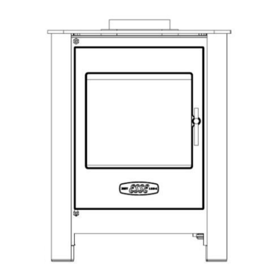
Summary of Contents for Esse G525
- Page 1 G500 VISTA/G525 MANUAL & REMOTE CONTROL GAS FIRED LOG EFFECT STOVE INSTALLATION,USER & SERVICING INSTRUCTIONS (TO BE LEFT WITH THE CUSTOMER) UK & IRELAND G500 VISTA-LR/G525-LR For use in UK & Ireland on Natural gas at a supply pressure of 20mbar or...
-
Page 2: Table Of Contents
All surfaces except the control knob and battery housing are considered to be working surfaces. The stove should not be used for any other purpose than as a room heater and a decorative stove. Page 2 G500V-G525-REM-I04-020317... -
Page 3: Technical Information
TECHNICAL INFORMATION Natural Gas Settings G500-Vista/G525 GATEGORY HEAT INPUT (NETT) 4.87kW/3.33kW HIGH/LOW SUPPLY PRESSURE 20 mbar INJECTOR SIZE 82/340 GAS CONNECTION 8mm O.D. Tube NOX CLASS EFFICIENCY CLASS COUNTRIES OF CH, CZ, ES, FI, GB, DESTINATION IE, IT, PT & SE... -
Page 4: Dimensions And Clearances
DIMENSIONS AND CLEARANCES Fig 1a – G500-Vista Log Dimensions Page 4 G500V-G525-REM-I04-020317... - Page 5 Fig 1b – G500-Vista Log Dimensions Page 5 G500V-G525-REM-I04-020317...
- Page 6 Fig 1c – G525 Log Dimensions Page 6 G500V-G525-REM-I04-020317...
-
Page 7: Installation
It is recommended that a minimum height of 610mm from the stove should be established before any significant change in the direction of the flue. An optional rear flue attachment is available as an accessory from www.esse.com (see Fig.1b). Page 7... - Page 8 The gas supply should incorporate a service tap, be purged and any loose matter removed. Connect the gas supply pipe and check for gas soundness. TTB (Thermocouple interrupter) Fig. 2 Shows the TTB connection on the back of the gas valve. Page 8 G500V-G525-REM-I04-020317...
- Page 9 Locate LOG2 into position as shown (Fig 6). Locate LOG3 into position as shown (Fig 7). Locate LOG1 into position as shown (Fig 8) Close the stove door. Tighten the door locking screw. Fig. 3 LOG 1 LOG 1 LOG 2 LOG 3 Page 9 G500V-G525-REM-I04-020317...
- Page 10 Fig. 4 Fig. 5 LOG 1 Fig. 6 Fig. 7 LOG 2 LOG 3 Fig. 8 Fig. 9 LOG 1 Page 10 G500V-G525-REM-I04-020317...
-
Page 11: Commissioning The Stove
Apply a smoke match along the bottom edge of the draught diverter. The installation is satisfactory if the smoke is drawn into the stove. If in doubt wait a further 10 minutes and then repeat the test. Page 11 G500V-G525-REM-I04-020317... -
Page 12: Customer Briefing
Stress that no extra logs must be added over and above those supplied with the appliance and that any replacements must only be authorized Esse spares. Recommend that the stove is regularly serviced and the flue system checked by qualified persons. -
Page 13: General Notes
150mm or less deep shelf there is at least 400mm clearance above the top of the stove. The stove should not be used for any other purpose than as a room heater and a decorative stove. Page 13 G500V-G525-REM-I04-020317... -
Page 14: Positioning The Logs
Locate LOG3DMR into position as shown (Fig 10). Locate LOG4DMR into position as shown (Fig 11). Locate LOG4DMR into position as shown (Fig 12). Close the stove door. Tighten the door locking screw. Fig. 10 LOG 1 LOG 1 LOG 2 LOG 3 Page 14 G500V-G525-REM-I04-020317... - Page 15 Fig. 11 Fig. 12 LOG 1 Fig. 13 Fig. 14 LOG 2 LOG 3 Fig. 15 Fig. 16 LOG 1 Page 15 G500V-G525-REM-I04-020317...
-
Page 16: Stove Controls
This stove is fitted with a gas valve which can be operated via the control unit located behind the right hand foot of the stove, or using the remote control if supplied. Fig 17 - Control unit Page 16 G500V-G525-REM-I04-020317... - Page 17 Burner in operation: Use this button to increase the power level. Battery box: Insert here 3x AA-type Alkaline batteries. Thermocouple connector. High voltage and flame sensing output. Gas inlet. Pilot burner outlet. Main burner outlet. TTB connection socket. Control unit mounting points. Page 17 G500V-G525-REM-I04-020317...
- Page 18 (N.B. Keep a grip of handset to keep it unlocked, to continue to operate the command buttons). Fig 18 – Remote control Page 18 G500V-G525-REM-I04-020317...
-
Page 19: Operating The Stove
To start the fire, with one hand grasp around the rear and both sides of the button area control. The green unlock light will illuminate. Keep the handset held to keep the control unlocked, to enable operation of the buttons. Page 19 G500V-G525-REM-I04-020317... - Page 20 Similarly if it is released too soon before the word pilot appears, the command is also ignored. With this system, the control has been designed to ensure that only intended ignition of the fire occurs.) To stop – with handset held to unlock it, press then release power button. Page 20 G500V-G525-REM-I04-020317...
- Page 21 (AM or PM) display. Press the + or – button on the handset to toggle between the two settings. When you are ready to confirm the setting you want press the “SET” button to progress to setting the day of the week. Page 21 G500V-G525-REM-I04-020317...
- Page 22 Setting the Hour Press and release the + or – button to change the hour to the correct hour and press set to store and to move to setting the minute. Repeat this for setting the minutes. Page 22 G500V-G525-REM-I04-020317...
- Page 23 + button only on the Control unit for around 5 seconds. The handset will flash and make a noise to help you to locate it. Once you pick up and grasp the handset to unlock it, the Control unit will detect this and so the sound stops. Page 23 G500V-G525-REM-I04-020317...
- Page 24 Press then release the + (or – button) to change the display to CA1 and press and release the SET button again. The word TESC will appear in the window to show that this handset is now reset and ready to pair again. Page 24 G500V-G525-REM-I04-020317...
- Page 25 “TESC” shown, then too much time has passed before pressing “SET” and so the handset has not paired yet. Simply repeat pairing again. N.B. Only ever press + and - buttons together when pairing handsets. If done afterwards this will break the Page 25 G500V-G525-REM-I04-020317...
- Page 26 When the word “pilot” appears at the bottom left hand corner of the display, immediately release the power button). The fire will now light and adjust the power settings to reach and maintain the set temperature. Page 26 G500V-G525-REM-I04-020317...
-
Page 27: Spillage Monitoring System
Then press again in the same way to attempt a new start cycle. The error code must be cleared for the fire to function correctly. Servicing must only be carried out by competent personal that have current qualifications and accreditation (i.e. Gas safe). Page 27 G500V-G525-REM-I04-020317... - Page 28 Page 28 G500V-G525-REM-I04-020317...
- Page 29 Page 29 G500V-G525-REM-I04-020317...
- Page 30 Page 30 G500V-G525-REM-I04-020317...
-
Page 31: Cleaning
Close the stove door; replace the screw securing the door handle or door. Check the supply pressure as described in the TECHNICAL INFORMATION section (p.3). Ensure correct operation of the flue as described in CHECK FOR SPILLAGE section (p.10). Page 31 G500V-G525-REM-I04-020317... -
Page 32: 10. Guarantee
Your ESSE is guaranteed against defects arising from faulty manufacture for 2 years when supplied by an ESSE Specialist. Upon registration of the warranty, ESSE will extend the guarantee period to 5 years from purchase. Your details must be registered with us by either returning the completed warranty card or by completing registration on-line at www.esse.com. - Page 33 Page 33 G500V-G525-REM-I04-020317...
- Page 34 Page 34 G500V-G525-REM-I04-020317...
- Page 35 Page 35 G500V-G525-REM-I04-020317...
- Page 36 ESSE Engineering Limited, Ouzledale Foundry, Long Ing, Barnoldswick, Lancashire BB18 6BJ Tel. 01282 813 235, Fax: 01282 816 876 Website and On-line Store http://www.esse.com Page 36 G500V-G525-REM-I04-020317...
Need help?
Do you have a question about the G525 and is the answer not in the manual?
Questions and answers