
Related Manuals for Esse 200 Series


Summary of Contents for Esse 200 Series
- Page 1 OIL FIRED STOVES INSTALLATION & SERVICING INSTRUCTIONS 200 Series Kingston New Zealand READ THESE INSTRUCTIONS AND SAVE FOR REFERENCE...
-
Page 2: Table Of Contents
CONTENTS Technical Information Important Notes Dimensions Installation Installation of the stove Chimney installation Ventilation Oil supply Positioning of the logs Installing the stove Customer briefing Trouble-shooting chart Spare parts TECHNICAL INFORMATION FUEL – Set for either Kerosene or Diesel – USE only the correct oil (Check data plate). -
Page 3: Dimensions
DIMENSIONS When the stove is unpacked the restrictor plate handle will need positioning in the vertical position. Hold the handle in the vertical position and tighten the lock nut as shown below. Oil burning appliances shall be connected to flues having sufficient draft at all times, to assure safe and proper operation of the burner. -
Page 4: Installation
INSTALLATION Install the stove in accordance with the requirements given below. If a concealed oil connection is to be made, prepare pipe work prior to installing the stove. Fit the four adjustable feet provided to each of the cast iron legs. INSTALLATION OF THE STOVE The stove can be installed in any adequate area suitable for solid fuel fires and stoves. -
Page 5: Ventilation
External flues of asbestos or cast iron pipe should not be used. Excessive exposure will result in heat loss and poor performance. Means of sweeping should be included. IMPORTANT For the burner to function correctly at maximum efficiency a steady flue draft not exceeding 0.12”... -
Page 6: Positioning Of The Logs
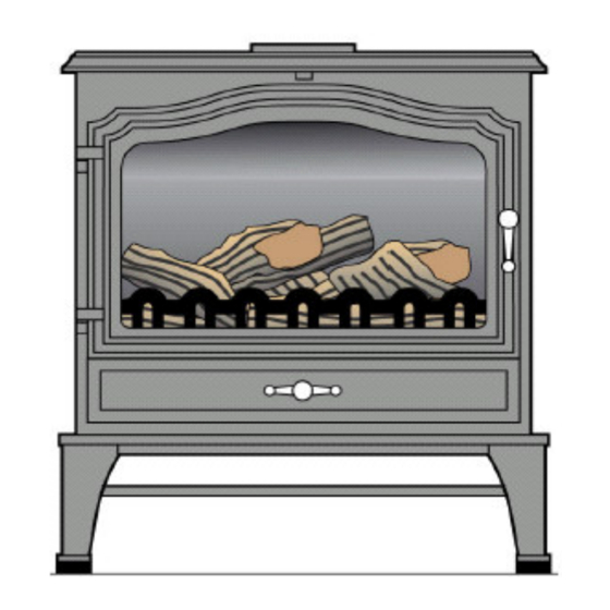
Figure 2. Oil connection POSITIONING THE LOGS Open the stove door. Spread the vermiculite supplied evenly around all four edges of the burner pot. Do not allow vermiculite to fall into the burner pot. Position log No: 1 at the rear of the burner as shown. - Page 7 Position log No: 2 and No: 3 as shown. Position log No: 4 and Log: 5 as shown. Position log No: 6 and No: 7 as shown.
- Page 8 Position log No: 8 as shown. Close the stove door. INSTALLING THE STOVE The installation should be inspected to ensure that the work is complete and the workmanship satisfactory. No stove should be installed if any part of the installation does not comply with relevant standards and regulations. It is recommended that the following procedure is carried out to ensure that the oil is free of contaminates (e.g.
- Page 9 Operating the Stove Pull the flue baffle handle fully forwards to the open position (Fig: 2). Lift up the oil valve arming lever and release (Fig:2 and Fig:5). Remove the burner chamber door and remove the burner lighting plug (Fig: 3).
- Page 11 CUSTOMER BRIEFING Hand these instructions and the User Instructions to the Customer. Advise the Customer how to use the stove. Do not attempt to re-light the stove until it is cold. Point out that the operating procedure is in the User Instructions.
- Page 14 Glen Dimplex Australasia Ltd, 38 Harris Road, P.O. Box 58473, Greenmount, Auckland, New Zealand. Phone: (09) 274 8265 Fax: (09) 274 8472 sales@glendimplex.co.nz esse Firemaster, PO Box 4, Barnoldswick, Lancashire, BB18 6BN www.esse.com Tel: 01282 813 235 Fax: 01282 816 876...
Need help?
Do you have a question about the 200 Series and is the answer not in the manual?
Questions and answers