Esse 500 Installation & Servicing Instructions Manual
Flueless cat gas fired stove series
Hide thumbs
Also See for 500:
- Installation & user's instructions (6 pages) ,
- Installation & user's instructions (32 pages)
Table of Contents
Advertisement
Quick Links
Esse Engineering Limited, Long Ing, Barnoldswick, Lancashire BB18 6BN
Tel: 01282 813235 Fax: 01282 816876 e-mail: enquiries@esse.com
Website: http://www.esse.com On-line Store: http://www.esseparts.com
12/09 (PP)
INSTR.ST-515FG/i
FLUELESS CAT GAS FIRED STOVE SERIES
FLUELESS CAT GAS FIRED STOVE SERIES
FLUELESS CAT GAS FIRED STOVE SERIES
FLUELESS CAT GAS FIRED STOVE SERIES
Installation & SERVICING INSTRUCTIONS
GB
500/525
(TO BE LEFT WITH THE CUSTOMER)
UK & IRELAND
IE
Advertisement
Table of Contents

Related Manuals for Esse 500


Summary of Contents for Esse 500
- Page 1 FLUELESS CAT GAS FIRED STOVE SERIES INSTALLATION & SERVICING INSTRUCTIONS (TO BE LEFT WITH THE CUSTOMER) UK & IRELAND Esse Engineering Limited, Long Ing, Barnoldswick, Lancashire BB18 6BN Tel: 01282 813235 Fax: 01282 816876 e-mail: enquiries@esse.com Website: http://www.esse.com On-line Store: http://www.esseparts.com...
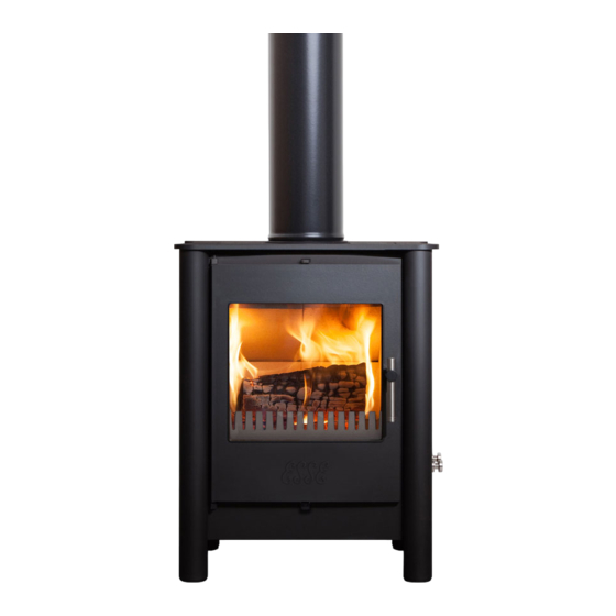
- Page 2 The main burner will automatically switch from low to off as the room temperature continues to rise. As the room temperature cools the main burner will Fig. 1 - 500 Series switch from off to low and then adjust its input as required. There is a thermostat manual override lever also fitted.
- Page 3 NOTE For the 500 series the back of the stove may be installed directly against a All dimensions are in millimetres non-combustible wall. For the 525 stove it is recommended there should be a minimum clearance of 25mm (1in) between the top plate and a non-combustible wall.
- Page 4 An increase in height of 25mm is required for every 12.5mm of additional shelf depth. For shelves that are too low, protective devices 500 Series Stove can be used such as metal heat deflectors, but it must be assured that the shelf does not Remove the door locking screw (if fitted) located behind the spinner (Fig.
- Page 5 Fig. 8 - Control Valve Connections and Rate Screws e) Turning the Pilot OFF From any heat setting or the PILOT POSITION depress control knob fully and turn clockwise to OFF position. Fig. 5 - Controls on 500/525 Valve...
- Page 6 Point out the explanation of this system in the User Instructions. Advise that if the monitoring system repeatedly shuts off the stove, it should be switched off Should any replacement components be requested they must only be authorised ESSE and a specialist consulted.
Need help?
Do you have a question about the 500 and is the answer not in the manual?
Questions and answers