Table of Contents
Advertisement
Quick Links
Advertisement
Table of Contents

Related Manuals for Westermo Lynx-3510-F2G-T8G-LV


Summary of Contents for Westermo Lynx-3510-F2G-T8G-LV
- Page 1 Lynx 3000 Series Industrial gigabit switch...
-
Page 2: Table Of Contents
4.5. Cable Strap ................ 19 4.6. Functional Earth Connection ..........20 4.7. Cooling ................21 5. Specifications ................22 5.1. Interface Specifications ............22 5.2. Type Tests and Environmental Conditions ......... 27 6. Revision Notes ................31 Lynx 3000 Series... -
Page 3: General Information
Westermo reserves the right to revise this document or withdraw it at any time without prior notice. Under no circumstances shall Westermo be responsible for any loss of data or income or any special, incidental, and consequential or indirect damages howsoever caused. -
Page 4: Safety And Regulations
No personal injury Minor damage to the order to avoid misuse of product the product, confusion or misunderstanding NOTICE Used for highlighting general, No personal injury Minor damage to the but important information product NOTE Table 1. Warning levels Lynx 3000 Series... -
Page 5: Safety Information
Before energising and connecting communication cables to the product, ensure a protective earthing conductor is first connected to the protective earthing terminal (only valid for metallic housings). Westermo recommends a cross-sectional area of at least 4 mm Upon removal of the product, disconnect the product from the power supply and all other communication ports before disconnecting the protective earthing conductor. - Page 6 (e.g. use a wrist strap). CABLE TEMPERATURE RATING FOR FIELD TERMINAL WIRES There may be a requirement on the minimum temperature rating of the cable to be connected to the field wiring terminals, see chapter Interface Specifications. Lynx 3000 Series...
-
Page 7: Care Recommendations
If the product is not working properly, contact the place of purchase, the nearest Westermo distributor office or Westermo technical support. 2.4. Product Disposal This symbol means that the product shall not be treated as unsorted municipal waste when disposing of it. -
Page 8: Fcc Part 15.105 Class A Notice
2.5.4. Simplified Declaration of Conformity Hereby, Westermo declares that this product is in compliance with applicable EU directives and UK legislations. The full declaration of conformity and other detailed information is available at www.westermo.com/support/product-support. -
Page 9: Product Description
These tools can be used to build networks in compliance with the IEC 62443 standard, which defines technical security requirements for data communication network components. The Lynx 3000 switches are ideal for mission critical applications within transportation, manufacturing, energy, smart cities and other applications. Lynx 3000 Series... -
Page 10: Available Models
+70 °C 3627-0540 Lynx-3510-F2G2.5-T8G-LV -40 to +70 °C 3627-0550 Lynx-3510-E-F2G2.5-T8G-LV -40 to +70 °C 3627-0560 Lynx-3310-F2G-T8-LV -40 to +70 °C 3627-0570 Lynx-3310-E-F2G-T8-LV -40 to +70 °C 3627-0580 Lynx-3510-F2G2.5-P8G-LV -40 to +70 °C 3627-0590 Lynx-3510-E-F2G2.5-P8G-LV -40 to +70 °C Lynx 3000 Series... -
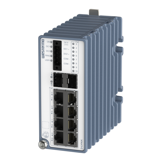
Page 11: Hardware Overview
Ethernet TX ports or Ethernet TX ports (PoE+) I/O port Micro SD Console port Protective earth terminal Label with data matrix Depending on model The base MAC address and production date of the product is included in the front label data matrix. Lynx 3000 Series... -
Page 12: Connector Information
For voltage/current, see Interface Specifications. The Digital in is an opto-isolated digital input, which can be used to monitor external events. For voltage/current, see Interface Specifications. Lynx 3000 Series... -
Page 13: Console Port
In the event of contamination, the optical connectors in the SFP transceivers should only be cleaned by the use of forced nitrogen and some kind of cleaning stick. Recommended cleaning fluids are methyl-, ethyl-, isopropyl- or isobutyl alcohol, hexane or naphtha. Lynx 3000 Series... - Page 14 They are very sensitive to dust and dirt. If the fibre optic cable is disconnected from the product, a protective plug must be used on the transmitter/receiver. The protective plug must be kept on during transportation. The fibre optic cable must be handled the same way. Lynx 3000 Series...
-
Page 15: Led Indicators
Location indicator ("Here I am"). Activated when FLASH connected to WeConfig tool, or open request from web or/and CLI. No PoE output GREEN PoE output active GREEN Error or negotiating power output FLASH Only available for PoE models Table 5. LED indicators Lynx 3000 Series... -
Page 16: Dimensions
3.6. Dimensions Dimensions are stated in mm and are regardless of model. 42 min. Illustrated by a Lynx-3510-F2G-P8G-LV Figure 6. Dimensional drawing Lynx 3000 Series... -
Page 17: Installation
4.2. Removal of Product To remove the product, either push the support pin down and towards the front of the product, or press down the support at the back with a screwdriver and lift off the product from the DIN-rail. Lynx 3000 Series... -
Page 18: Panel Mounting
Figure 8. Removal of product by pushing the support pin Figure 9. Removal of product with screwdriver 4.3. Panel Mounting The product can be mounted to a panel with cage nuts made for 5.3 mm square holes with a 1-1.6 mm panel thickness. Lynx 3000 Series... -
Page 19: Wall Mounting
Illustrated by a Lynx-3510-F2G-P8G-LV Figure 11. Wall mounting with screws 4.5. Cable Strap The product has loops on the right side that cable straps can be attached to, to help collecting the connector cables and lead them aside. Lynx 3000 Series... -
Page 20: Functional Earth Connection
For correct function, the earth connection needs to be properly connected to a designated PE rail. Torx: T25 and torque: 3.2 Nm. 54 V DC1 + DC2 + RING COM- USR1 COM- Illustrated by a Lynx-3510-F2G-P8G-LV Figure 13. Earth connection Lynx 3000 Series... -
Page 21: Cooling
/ right the unit. Spacing is recommended for the use of unit in full operating temperature range and service life. 10mm 10mm 54 V DC1 + DC2 + RING COM- USR1 COM- Illustrated by a Lynx-3510-F2G-P8G-LV Figure 14. Minimum spacing of product Lynx 3000 Series... -
Page 22: Specifications
6.3.1 in EN/IEC/UL 61010-1. The voltage at the accessible part does not exceed the limit of 6.3.2 in EN/IEC/UL 61010-1 during a single fault condition. Measured for 1 second at startup Lynx 3000 Series... - Page 23 Circuit type SELV Maximum voltage/current 60 VDC, I ≤ 2.9 mA at 60 VDC Voltage levels Logic one: >8 VDC Logic zero: <5 VDC External circuits connected to I/O connectors shall be SELV-rated circuits, galvanic isolated from mains. Lynx 3000 Series...
- Page 24 Full or half, manual or auto Circuit type SELV Transmission range Up to 100 m with CAT5e cable or better Isolation All other ports Cabling Shielded cable CAT5e or better is recommended Conductive chassis 10/100/1000 Mbit/s ports are no. 3 to 10 Lynx 3000 Series...
- Page 25 IEEE std 802.3 Data rate 1 Gbit/s, 2.5 Gbit/s Duplex Full or half, manual or auto Transmission range Depending on transceiver Connector SFP slot holding fibre transceiver SFP ports are 1 to 2. 1 Gbit/s tranceiver supported Lynx 3000 Series...
- Page 26 Up to 480 Mbps (high-speed mode). Emulates UART, settings 115200 bps. Circuit type SELV Maximum supply current 100 mA Connector USB-C connector in device mode Micro SD Electrical specification Secure Digital 2.0 Circuit type SELV Maximum supply current 100 mA Connector Micro SD connector Lynx 3000 Series...
-
Page 27: Type Tests And Environmental Conditions
CISPR 22 Ethernet ports Class A (0.15 to 30 MHz) Compass safe IEC 60945 Enclosure Minimum safe distance to: distance standard compass: 15 cm steering compass: 10 cm Power supply failure DNV-CG-0339 Power port -100%, 30 s Lynx 3000 Series... - Page 28 I/O port to all 1500 VAC rms, 60 s (PoE models) other ports, incl. chassis DNV-CG-0339 Power port and 2250 VDC, 60 s Ethernet PoE IEEE 802.3 ports to all other ports, incl. chassis Table 6. EMC and electrical conditions Lynx 3000 Series...
- Page 29 5 to 2000 Hz, 3 x 1.5 h 60068-2-64 (random) Shock Operational 15 g/11 ms, 3 x 6 shocks 60068-2-27 Enclosure EN 61010-1 Aluminum Fire enclosure Weight 1100 gr Degree of protection EN 60529 Enclosure IP40 Cooling Convection Overvoltage EN/IEC OVC II category 61010-1 Lynx 3000 Series...
- Page 30 Method 3, 21 days corresponds to Harsh Industrial Environment G3 which is defined in ANSI/ISA 17.04: 2015 The power and I/O cables need to be fastened 200 mm or closer to the unit. The same recommendation applies to the Ethernet cables. Table 7. Environmental and mechanical conditions Lynx 3000 Series...
-
Page 31: Revision Notes
Non-PoE models added and their specific data information. Name changed to Lynx 3000 throughout the user guide. 2.5.1 Environmental: NEMA TS2 added, 3.5 LED Indicators updated. Rev. B 2022-09 Name changed to Lynx 3510 PoE throughout the user guide Rev. A 2022-04 First revision Lynx 3000 Series... - Page 32 Westermo • Metallverksgatan 6, SE-721 30 Västerås, Sweden Tel +46 16 42 80 00 Fax +46 16 42 80 01 E-mail: info@westermo.com www.westermo.com 6627-2210 REV C 2023 03 @ Westermo Network Technologies AB, Sweden...
Need help?
Do you have a question about the Lynx-3510-F2G-T8G-LV and is the answer not in the manual?
Questions and answers