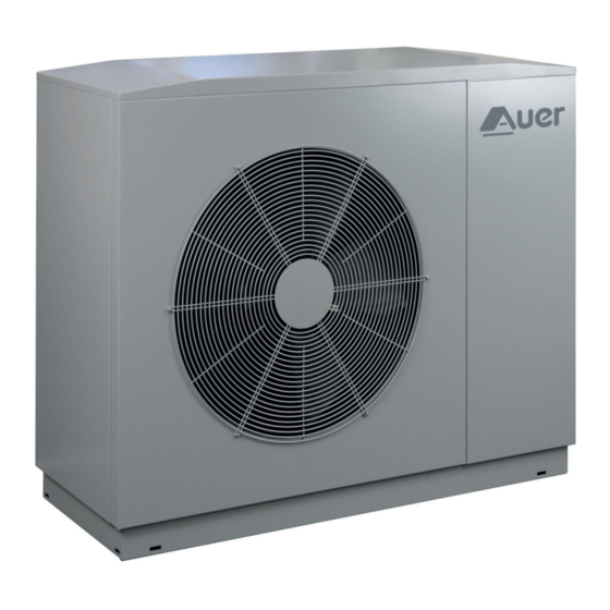
Table of Contents
Advertisement
Quick Links
Advertisement
Table of Contents

Summarization of Contents
1-SAFETY
General Safety Warnings
Covers risks from improper qualifications, use, electrocution, pressure relief valves, and material damage.
Applicable Areas and Regulations
Defines intended use, applicable areas, and compliance with rules and regulations.
Maintenance and Troubleshooting Guidance
Outlines basic maintenance and troubleshooting advice for the pilot unit.
REFRIGERANT CIRCUIT
Professional Intervention Requirements
Work on refrigerant circuits requires certified professionals adhering to safety standards.
R290 Refrigerant Safety
R290 refrigerant is flammable; follow safety precautions for handling and potential leaks.
2-IMPORTANT PRELIMINARIES
Document Conservation and Symbols
Manual must be kept and symbols explained for user reference and legal evidence.
Abbreviations and Acronyms
Lists common abbreviations used in the manual for clarity.
3-DELIVERY AND STORAGE
Delivery and Initial Checks
Material is transported at recipient's risk. Verify all received elements and check for damage.
Storage and Transport Guidelines
Admissible storage temperatures are -20°C to +60°C. Follow manual for safe handling during transport.
4-INTRODUCTION
Unit Operation and Function
Explains the heat pump's closed system operation using refrigerant for energy transfer.
Included and Optional Accessories
Lists components delivered with the unit and available accessories for purchase.
5-INSTALLATION
Standard Installation Configuration
Heat pump must be installed outside with clear airflow and protection from winds.
5.2 - PLACEMENT
Installation Location and Noise Considerations
Discusses optimal placement, airflow requirements, and how installation affects noise levels.
Safety Perimeter Requirements
Defines safety zones around the unit due to flammable refrigerant and potential accumulation.
5.2.2.2 - SECURITY AREA IN FRONT OF A WALL
Accepted and Prohibited Installation Sites
Illustrates acceptable and unacceptable locations relative to buildings and neighboring properties.
5.3 - SETTING UP
Condensate Evacuation Procedures
Details how to ensure proper drainage of condensed water, including automatic defrosting.
5.5 - HYDRAULIC INSTALLATION
Hydraulic Connections on Installation
Emphasizes proper pipe sizing between Heat Pump and Pilot and the need for thermal insulation.
5.5.2 - HYDRAULIC CONNECTION BETWEEN HEAT PUMP AND PILOT
HTi 11 & 14kW Hydraulic Connections
Specific instructions and diagrams for connecting the HTi 11 & 14kW models using the supplied kit.
5.5.3 - HEAT PUMP WATER INLET FILTER
Connecting to the Power Supply
Guidelines for connecting the heat pump to the electrical power supply, including general recommendations.
5.6.2 - ACCESSING THE CONNECTION TERMINALS
Power Supply Connection Recommendations
Advice on checking power, cables, and ratings, and compliance with regulations for system connection.
Single-Phase Power Connection
Details for connecting single-phase models, including voltage, frequency, and cable sizing.
5.6.4.2 - THREE-PHASE CONNECTION
Phase Controller Relay Functionality
Explains the role of the phase controller relay in three-phase units to prevent damage from phase faults.
5.6.5 - COMMUNICATION BUS CABLE
Heat Pump to Pilot Connection
Diagram and instructions for connecting the communication bus cable between the heat pump and the pilot.
6 - MAINTENANCE AND TROUBLESHOOTING
General Maintenance Guidelines
Emphasizes regular maintenance for performance and checks for leaks and proper operation.
Specific Maintenance Tasks
Details maintenance for hydraulic circuit, heat pump, and electrical components.
Consulting Performance Meters
Explains how to access and read performance data from the pilot's display.
6.6 - SENSOR DATA CURVE CHARTS
Sensor Resistance vs. Temperature Data
Charts showing sensor resistance values versus temperature for various sensors.
6.8 - DECOMMISSIONING
Interim and Final Decommissioning
Procedures for temporary and permanent product shutdown, requiring professional handling.
6.9 - RECYCLING AND DISPOSAL
Refrigerant Disposal Procedures
Guidelines for proper disposal of R290 refrigerant by qualified personnel following safety rules.
8 - WARRANTY
Warranty Coverage
Outlines the warranty period, conditions for validity, and what is covered.
General Limitations of Warranty
Excludes damage from misuse, incorrect installation, natural disasters, and insufficient maintenance.
Specific Warranty Exclusions
Lists exclusions for heating water quality, handling, installation site, electrical, hydraulic, accessories, and maintenance.
APPENDIX
Technical Specifications and Performances
Provides detailed technical data and performance charts for various models.
General Characteristics and Dimensions
Lists general specifications like electrical supply, dimensions, weight, and flow rates.
Performance Data
Presents heating capacity and COP at different temperature conditions.
A4 - TREATMENT OF THE WATER IN THE HEATING CIRCUIT
Hydraulic Circuit Preparation and Filling
Mandatory rinsing of the circuit and using treated water from the drinking water network.
Heating Circuit Treatment Recommendations
Advises on cleaning and protecting the heating circuit against corrosion and limescale.
A7 - INTERNAL WIRING DIAGRAM
HTi70 11 & 14 kW Single-Phase Wiring
Wiring diagram for single-phase models, showing connections for PCB, compressor, and sensors.


Need help?
Do you have a question about the HTi70 14 and is the answer not in the manual?
Questions and answers