Table of Contents
Advertisement
Quick Links
HRC
High-temperature, modulating
70
HRC
Heat Pump and Pilot
Energy Effi cient
Installation and operating instructions
Manual ref: 1871442
Edition n°: 15.356
The information contained in this document is non-contractual. Auer reserves the right to modify all technical data and equipment of our products without prior notice.
70
HRC
Pilot
70
High-temperature
HRC
70
modulating
heat pump
70
HRC
17 single phase
Ref.151201
HRC
70
17 three phase
Ref.151211
70
HRC
20 three phase
Ref.151271
HRC
70
25 three phase
Ref. 151221
Made
in France
Advertisement
Table of Contents

Related Manuals for auer HRC70 20


Summarization of Contents
1 - PLEASE READ IMMEDIATELY
1.1 - Important information
Key information about the installation and operating instructions manual.
1.2 - Safety instructions and advice
Crucial safety guidelines and advice for the installation and use of the appliance.
1.3 - Delivery terms and conditions
Information regarding the terms and conditions for the delivery of the appliance.
1.4 - Storage and transport
Guidelines for the proper storage and transport of the Heat Pump and Pilot.
2 - INTRODUCTION
2.1 - Standard configuration
Overview of the typical setup of the HRC70 Heat Pump and Pilot system.
2.2 - Operating
Explanation of how the Heat Pump and Pilot system operates.
2.3 - Accessories (included)
List and description of accessories provided with the Pilot unit.
2.4 - Accessories available to order
List and description of optional accessories that can be ordered.
3 - INSTALLATION
3.1 - Installing the HRC70
Instructions for the physical installation of the HRC70 Heat Pump unit.
3.1.1 - Installation site
Guidelines and requirements for selecting the optimal installation location for the Heat Pump.
3.1.2 - Installing the Pilot
Step-by-step instructions for installing the HRC70 Pilot unit.
3.2 - Plumbing connections
Guidance on making the necessary hydraulic connections for the installation.
3.2.1 - Hydraulic connections for the installation
Details on making the hydraulic connections between the Heat Pump and Pilot.
3.2.2 - Hydraulic connection : Heat Pump circuit
Details on the hydraulic connections for the Heat Pump circuit.
3.2.3 - Heat Pump and Pilot relief valve
Information on the pressure relief valves for the Heat Pump and Pilot.
3.2.4 - Desludging
Explanation of the desludging function and procedure.
3.2.5 - Heat Pump water inlet filter (supplied)
Information on the supplied water inlet filter for the Heat Pump.
3.2.6 - Heating circuit
General guidance and precautions for the heating circuit.
3.3 - Installation advice for different types of transmitters and different uses
Advice for various installation types and uses, including radiators, underfloor, and DHW.
3.4 - Electrical control connections
Instructions for making the electrical control connections for the system.
3.4.1 - Connecting the Heat Pump control
How to connect the Heat Pump's control system to the Pilot.
3.4.2 - Connecting the Pilot
Steps for connecting the Pilot to the power supply and controls.
3.5 - Connecting to power supply
Instructions for connecting the system to the electrical power supply.
3.5.1 - Recommendations for connecting the system to the power supply
Key recommendations for ensuring a safe and compliant power supply connection.
3.5.2 - Connecting the Pilot to the power supply
Instructions for connecting the Pilot to the electrical power supply.
3.5.3 - Connecting the HRC70 Heat Pump to the power supply
Detailed instructions for connecting the HRC70 Heat Pump to the power supply.
3.5.4 - Electrical protection for the compressors
Information on electrical protection measures for the system's compressors.
4 - APPLIANCE CONFIGURATION
4.1 - Control box
Overview and functions of the appliance's control box.
4.1.1 - Display screen: symbols and what they mean
Explanation of the symbols displayed on the control screen.
4.1.2 - Commonly displayed symbols
Common symbols encountered during operation and their meanings.
4.1.3 - Unlocking
Procedure to unlock the control box when it is locked.
4.1.4 - Language
How to change the language displayed on the control box.
4.2 - Installer Menu
Accessing and navigating the installer menu for configuration.
4.2.1 - Selecting the right back-up for the installation
Configuring the appropriate back-up system for the installation.
4.2.2 - CONFIGURATION of the HRC70 Heat Pump and circuits
Configuring the Heat Pump model and the heating/water circuits.
4.2.3 - SETTING operating parametres
Adjusting various operating parameters for the system.
4.2.4 - FORCED COMMAND of the system
Manually engaging system components for diagnostics or testing.
5 - USE
5.1 - Setting the date and time
How to set the date and time for automatic adaptation to heating modes.
5.2 - Displaying the control values
Accessing and viewing system data such as temperatures and pressures.
5.3 - User Menu
Navigating the user menu to access settings and view temperatures.
5.3.1 - Setting target temperatures
Adjusting target temperatures for different modes like Ambience, Eco, and Anti-freeze.
5.3.1.1 - Setting the AMBIENCE target temperature
How to set the desired ambient temperature.
5.3.1.2 - Setting the ECO target temperature
How to set the desired economy mode temperature.
5.3.1.3 - Setting the ANTI FREEZ target temperature
How to set the desired anti-freeze temperature.
5.3.1.4 - Setting the domestic hot water temperature
Setting the target temperature for domestic hot water production.
5.3.1.5 - Setting the SWIM. POOL temperature
Setting the target temperature for swimming pool water.
5.3.2 - Setting a VACATION period
Programming a vacation mode to maintain frost protection.
5.3.3 - Temporary OVERRIDE of the programmed heating mode
How to temporarily override the current heating mode.
5.3.4 - BOOST function
Using the BOOST function to speed up temperature rise.
5.3.5 - Selecting SUMMER / WINTER mode
Manually switching between summer and winter operating modes.
5.3.6 - Selecting the LANGUAGE
Instructions for selecting the display language.
5.3.7 - BEEP alert
Configuring audible alerts for dial presses.
5.3.8 - Accessing the INST. MENU
Procedure to access the installer menu.
6 - MAINTENANCE AND REPAIRS
6.1 - General information
General advice and checks for maintaining the appliance.
6.2 - Hydraulic circuit maintenance
Maintenance procedures for the hydraulic circuit.
6.2.1 - Water circuit condensate drainage
Checking and cleaning the condensate drainage system.
6.2.2 - HRC70 Pilot
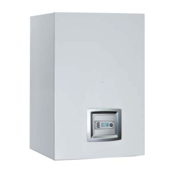
Maintenance recommendations for the HRC70 Pilot unit.
6.2.3 - Heating circuit maintenance
Specific maintenance tasks for the heating circuit.
6.3 - Heat Pump maintenance
Maintenance recommendations for the HRC70 Heat Pump unit.
6.4 - Electrical components maintenance
Procedures for maintaining electrical components safely.
6.5 - Checking operating temperatures
How to check operating temperatures via the control readings.
6.5.1 - Accessing control readings and internal / external controls
Steps to access and view internal and external control readings.
6.5.2 - Accessing calculated data
How to access and view calculated data from the installer menu.
6.5.3 - Accessing the meters
How to access and view system meters and counters.
6.6 - Errors which are not signalled by error message or alert
Troubleshooting for issues not indicated by error messages or alerts.
6.7 - Compressor start-up faults
Identifying and resolving common compressor start-up faults.
6.8 - Alerts and errors which are signalled by the appliance
Understanding and responding to appliance alerts and error signals.
6.9 - Error messages
A comprehensive list of error messages and their corresponding solutions.
6.9.1 - Errors and solutions
Detailed list of error messages and solutions for system faults.
6.9.2 - Operating in case of error
How to operate the appliance in case of an error.
6.10 - Sensor data curve charts
Charts showing sensor data curves for various system components.
6.10.1 - Sensor Data Curve Charts
Charts showing sensor data curves for various system components.
6.10.2 - Outdoor sensor
Resistance values for the outdoor sensor at different temperatures.
6.11 - Decommissioning and disposal
Procedures for safely decommissioning and disposing of the appliance.
7 - PARTS
7.1 -HRC70 Heat Pump
List of part numbers and products for the HRC70 Heat Pump.
7.2 - Electrical boxes
Details of electrical boxes for different Heat Pump models.
7.3 - HRC70 Pilot
List of part numbers and products for the HRC70 Pilot.
8 - WARRANTY
8.1 - Warranty limits
General conditions and limitations of the product warranty.
8.1.1 - General information
General terms and exclusions from the warranty coverage.
8.1.2 - Cases (non limited) for exclusion from warranty
Specific situations that void the warranty.
8.1.2.1 - Heating circuit water
Exclusions related to heating circuit water quality and treatment.
8.1.2.2 - Handling
Exclusions related to improper handling of the appliance.
8.1.2.3 - Installation site
Exclusions related to unsuitable installation sites or methods.
8.1.2.4 - Electrical connections
Exclusions related to incorrect electrical connections.
8.1.2.5 - Hydraulic connections
Exclusions related to improper hydraulic connections.
8.1.2.6 - Accessories
Exclusions related to the use of non-approved accessories.
8.1.2.7 - Maintenance
Exclusions related to improper or lack of maintenance.
APPENDICES
A1 - Dimensions
Physical dimensions of the HRC70 Heat Pump and Pilot.
A1.1 -HRC70 Heat Pump
Detailed dimensions of the HRC70 Heat Pump unit.
A1.2 -HRC70 Pilot
Detailed dimensions of the HRC70 Pilot unit.
A2 - Technical data
Technical specifications for the HRC70 Heat Pump and Pilot.
A2.1 -HRC70 Heat Pump
Technical specifications for the HRC70 Heat Pump models.
A2.2 - HRC70 Pilot
Technical specifications for the HRC70 Pilot unit.
A3 - Frost protection
Measures and advice for protecting the system from frost damage.
A4 - Sizing the expansion vessel
Guidelines for correctly sizing the expansion vessel for the installation.
A5 - Programming heating modes
How to program different heating modes and schedules.
A5.1 - Creating a new programme
Step-by-step guide to creating new heating programmes.
A5.2 - Copying existing programmes
Instructions for copying existing programmed heating schedules.
A5.3 - Changing a programme
How to modify existing programmed heating schedules.
A5.4 - View programme
How to view programmed heating schedules.
A6 - Heating circuit water treatment
Guidelines for treating heating circuit water, including rinsing and additives.
A6.1 - Preparing the hydraulic circuit (rinsing)
Procedure for rinsing the hydraulic circuit before filling.
A6.2 - Water for filling
Recommendations for the type of water to use for filling the circuit.
A6.3 - Heating circuit treatment
Advice on protecting the heating circuit from corrosion and limescale.
A6.4 - Frost protection
Measures for frost protection, especially when no back-up is available.
A7 - Performance tables
Performance data tables for the Heat Pump models.
A7.1 - HRC70 Heat Pump, 17kW
Performance data tables for the 17kW HRC70 Heat Pump.
A7.2 - HRC70 Heat Pump, 20kW
Performance data tables for the 20kW HRC70 Heat Pump.
A7.3 - HRC70 Heat Pump, 25kW
Performance data tables for the 25kW HRC70 Heat Pump.
Hydraulic schematic diagram -1 RADIATOR CIRCUIT- -swimming pool possible-
Schematic showing hydraulic connections for a radiator circuit with a possible swimming pool.
Hydraulic schematic diagram -1 UNDERFLOOR HEATING CIRCUIT- - pool possible-
Schematic showing hydraulic connections for underfloor heating with a possible swimming pool.
Hydraulic schematic diagram -2 RADIATOR CIRCUITS- -pool possible-
Schematic showing hydraulic connections for two radiator circuits with a possible swimming pool.
Hydraulic schematic diagram -2 UNDERFLOOR CIRCUITS - -pool possible-
Schematic showing hydraulic connections for two underfloor heating circuits.
Hydraulic schematic diagram -1 RADIATOR CIRCUIT/ + DHW- -pool possible-
Schematic for radiator circuit with DHW and possible swimming pool.
Hydraulic schematic diagram -1 RADIATOR CIRCUIT + POOL-
Schematic for radiator circuit with a swimming pool.
Hydraulic schematic diagram -1 POOL CIRCUIT + DHW -
Schematic for pool circuit with DHW.
Hydraulic schematic diagram -1 DIRECT CIRCUIT and 1 MIXED CIRCUIT- with optional 2nd circuit at lower temperature (Ref.751014) -pool possible-
Schematic for direct and mixed circuits with optional low-temp circuit.
Hydraulic schematic diagram -2 DIRECT CIRCUITS and 3rd MIXED CIRCUIT - with an optional 2nd circuit at a lower temperature (Ref.751014) and optional 2-way motorised valve for 1st direct circuit (Ref. 740022) -pool possible-
Schematic for multiple circuits with optional low-temp and motorised valve.
HRC70 Heat Pump - 17kW single phase- internal wiring diagram
Internal wiring diagram for the 17kW single-phase HRC70 Heat Pump.
HRC70 Heat Pump - 20kW three phase- internal wiring diagram
Internal wiring diagram for the 20kW three-phase HRC70 Heat Pump.
HRC70 Heat Pump - 17kW three phase- internal wiring diagram
Internal wiring diagram for the 17kW three-phase HRC70 Heat Pump.
HRC70 Heat Pump - 25kW three phase - internal wiring diagram
Internal wiring diagram for the 25kW three-phase HRC70 Heat Pump.
HRC70 Pilot electrical schematic diagram
Electrical schematic diagram for the HRC70 Pilot unit.
Key: HRC70 Pilot schematic electrical diagram • HRC70 Pilot internal wiring diagram
Key to symbols and connections for the HRC70 Pilot electrical diagrams.
HRC70 Pilot internal wiring diagram
Detailed internal wiring diagram for the HRC70 Pilot.
Need help?
Do you have a question about the HRC70 20 and is the answer not in the manual?
Questions and answers