Table of Contents
Advertisement
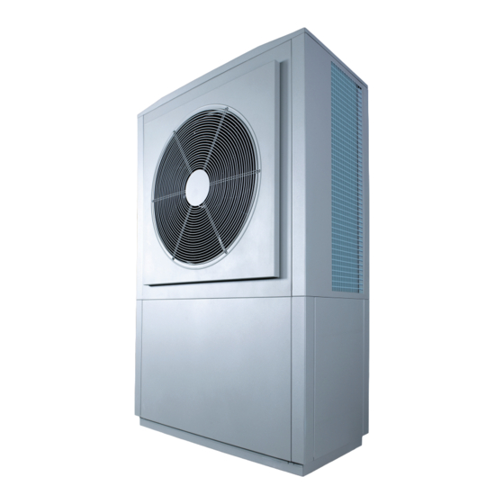
HRC
35kW
70
High temperature, modulating
Heat Pump
Installation and User manual
HRC
35 /2 t
70
Ref. 950280
Made in
France
Manual ref. : 1896823
Edition n
: 19.276
o
The information contained in this document is non-contractual. Auer reserves the right to modify the technical specifications or characterisitcs of any of their appliances without prior notice.
Advertisement
Table of Contents

Related Manuals for auer HRC70 35/2 t


Summary of Contents for auer HRC70 35/2 t
- Page 1 Ref. 950280 Made in France Manual ref. : 1896823 Edition n : 19.276 The information contained in this document is non-contractual. Auer reserves the right to modify the technical specifications or characterisitcs of any of their appliances without prior notice.
-
Page 2: Table Of Contents
TABLE OF CONTENTS TABLE DES MATIÈRES 6.1 - Limitations of warranty..............15 6.1.1 - General information ....................15 1 - PLEASE READ IMMEDIATELY ....... 3 6.1.2 - Cases (not limited to) for exclusion from warranty ........16 6.1.2.1 - Water from the heating circuit ............16 1.1 - Important information ...............3 6.1.2.2 - Handling ....................16 1.2 - Safety advice and instructions ............3... -
Page 3: Please Read Immediately
IMMEDIATELY transferred to the heating water for your home. AUER cannot be held responsible for any other usage of the appliance. The safety advice and instructions present in this document must 1.1 - Important information... -
Page 4: Delivery Terms And Conditions
2 - INTRODUCTION The HRC Heat Pump uses R290 refrigerant fluid. Given the flammable nature of the fluid, any work on the refrigerant circuit 2.1 - Standard configuration must be done with appropriate materials and by conforming to all regulations in effect. In case of handling of fluid (recovery, The ensemble is composed of an exterior unit (Monoblock high evacuation or refilling), the appliance must be switched off. -
Page 5: Installation
3 - INSTALLATION • The Heat Pump is designed to be installed OUTSIDE exclusively. 3.1 - Installing the Heat Pump • Any installation in an ENCLOSED and The Heat Pump must always be transported in a vertical position, UNVENTILATED space is PROHIBITED, unless including during installation. -
Page 6: Placement
3.1.3 - Noise levels 3.1.2 - Placement The Heat Pump is equipped with a large diameter fan so as to The Heat Pump is designed to be installed outdoors exclusively, while respecting a minimum of free space around the appliance allow for an appropriate air flow rate. -
Page 7: Condensates Drainage
Condensates recovery trough Grommet membrane (case b) Plastic cap (case a) Opening in base of concrete slab Back of the HRC heat pump Front of the HRC heat pump View from above showing the position of the opening in the concrete base (case a) 3.2 - Hydraulic installation 3.2.1 - Hydraulic connections on the installation THE NOISE-PREVENTION SCREEN MUST BE MADE... -
Page 8: Pressure-Relief Valves
3.2.4.1 - Backflow prevention device Heat Pump model 35kW Minimum nominal flow rate French law (articles 16.7 and 16.8 of the ‘‘Règlement Sanitaire 3500 L/h Départemental’’) stipulates that a type CB backflow prevention Maximum pressure 2.5 bars device must be installed. This device must be at different, non- regulated pressure zones, in accordance with the NF P 43-011 Minimum Ø... -
Page 9: Electrical Control Connections
3.3 - Electrical control connections The Heat Pump is pre-equipped with a non-polarised, 2-core sheathed cable (communication bus). This 10m cable is supplied with, and already connected to, the Heat Pump. It must be connected to the Pilot. If the connection needed is longer than 10m replace this cable with a 20m cable which is available to order (Ref. 751005). Diagram of connection to the Heat Pump with MANDATORY grounding of the Diagram of connection to the Heat Pump... -
Page 10: Connecting To The Power Supply
Note: 3.4 - Connecting to the power supply The wires must be stripped to the following lengths : Ensure that the power supply is sufficient to supply both the Heat - for the 2,5mm² control terminals: between 10 and 12mm Pump and the electrical back-up if necessary, taking into account - for the mains power terminal between 18 and 20mm any other domestic usage of electricity. -
Page 11: Hrc
Make sure to strip the cable before placing it into the 3.4.3. - HRC Heat Pump: terminals, and make sure that the copper is in good 400V three-phase connection condition. A method of disconnection must always be installed in Ground Neutral compliance with the installation rules. -
Page 12: Electrical Protection Of The Compressors
4 - MAINTENANCE AND 3.4.4 - Electrical protection of the compressors The HRC Heat Pump is equipped with progressive starters to TROUBLESHOOTING limit the intensity of the current when the motor starts-up, in compliance with the limits set by the NF C 15 100 standard, which is: 60A per phase in three-phase. -
Page 13: Maintenance On The Heat Pump
3 flashes operation • Contact your electricity provider to ensure proper sizing of the electrical network. Flashing • Contact an AUER approved technical centre. • Non-compliant power supply frequency 4 flashes • Contact your electricity provider. Flashing • Compressor blocked •... -
Page 14: List Of Spare Parts
Reference Description 5 - LIST OF SPARE PARTS 4993820 COMPRESSOR KIT CP1 35/2 5.1 - HRC Heat Pump 4993111 COMPRESSOR KIT CP2 35/2 1472803 PLATED HEAT EXCHANGER 1472833 DEHUMIDIFYING FILTER 4593064 4-WAY VALVE KIT 4993821 PRESSURE REDUCER KIT HRC 35/2 1239192 VAPOUR INJECTION VALVE HIGH PRESSURE SWITCH... -
Page 15: Electrical Boxes
Under no circumstances does a defective part warrant the replacement of the whole appliance. The warranty only applies to parts which we (AUER) identify as having been defective at manufacture. If necessary, the part or product should be returned to the manufacturer, but only with prior agreement from our technical department. -
Page 16: Cases (Not Limited To) For Exclusion From Warranty
6.1.2 - Cases (not limited to) for exclusion from APPENDICES warranty 6.1.2.1 - Water from the heating circuit A1 - Dimensions Cases (not limited) for exclusion from warranty: - Not rinsing the heating circuit - Using rain or well-water - Not treating the water for filling the heating circuit according to the instructions in the installer intruction manual. -
Page 17: A2 - Technical Specifications
A2 - Technical specifications A2.1 - General characteristics A2.2 - Performances 35 /2 three-phase 35 /2 three-phase Heating output 18,0 Maximum temperature 70°C Power consumption +7 / +35°C R290 refrigerant fluid 1,65 kg Heating output 16,0 Exterior air temperature range -20°C / +35°C Puissance absorbée +7 / +65°C... -
Page 18: A3 - Frost Protection
A3 - Frost protection PRODUCTS USED FOR THE TREATMENT OF HEATING WATER In cases where the HRC Heat Pump cannot operate (exterior MUST BE APPROVED BY THE LOCAL temperature is outside of the operating range), and a back-up is OR NATIONAL PUBLIC HYGIENE AND authorised (boiler or electrical), it will automatically be protected HEALTH AUTHORITY. - Page 19 RENDERING THE WARRANTY NULL AND VOID Do not use mono-ethylene glycol All deterioration of the appliance due to (toxic product) an inappropriate quality of water and/ or the presence of corrosion in the absence of Choose the % of glycol based on the minimum exterior treatment products as described above, and/ temperature to protect the water circuit from freezing (the or an improper purging of air of the installation...
-
Page 20: A5 - Hrc 70 - 35Kw Three-Phase-Heat Pump Internal Wiring
A5 - HRC - 35kW Three-phase-Heat Pump INTERNAL WIRING DIAGRAM green/yellow blue brown white white brown black white blue grey green/yellow brown orange black yellow brown blue blue blue blue g / y GROUND green/yellow green/yellow orange blue yellow blue 35kW HIGH TEMPERATURE HEAT PUMP installer manual... - Page 21 FAN wiring diagram brown blue blue G + Y brown TsPAC : Water outlet temperature sensor TePAC : Water inlet temperature sensor Tdégiv : De-icing temperature sensor Tair : Air intake temperature sensor Tcomp1 : Compressor 1 temperature sensor Tcomp 2 : Compressor 2 temperature sensor : Compressor 1 high pressure switch : Compressor 2 high pressure switch : Low pressure switch...
-
Page 22: A6 - Product Information Sheet
A6 - Product information sheet Fiche d'information technique produit (conformement au règlement UE n°811/2013) Product data sheet (in accordance with EU regulation no. 811/2013, 812/2013) AUER Marque / Brand name 35 / 2 t Modèle / Model Type / Type Pompe à... -
Page 23: A7 - Electricity Provider Information Form
A7 - Electricity provider information form This form is to given to the electricity provider for all preliminary evaluation for the installation of an HRC Heat Pump in case of an insufficient power grid. This table contains information on both electrical and technical data about the HRC Heat Pump. This technical data is provided in the table §... - Page 24 Rue de la République CS 40029 80210 Feuquières-en-Vimeu Spare parts department Tel. : 03 22 61 21 21 Fax : 03 22 61 33 35 E-mail : pieces@auer.fr Technical assistance department* E-mail : sav@auer.fr *Technical assistance service is reserved for professionals...
Need help?
Do you have a question about the HRC70 35/2 t and is the answer not in the manual?
Questions and answers