Table of Contents
Troubleshooting

Related Manuals for Toshiba RAV-HM1101CTP Series


Summarization of Contents
SAFETY CAUTION
Definition of Qualified Installer or Service Person
Defines the qualifications and knowledge required for installation and service personnel.
Protective Gear Requirements
Explanation of Safety Indications
Explains the meaning of DANGER, WARNING, and CAUTION indications.
Explanation of Illustrated Marks
Explains the meaning of illustrated symbols used in the manual and on the unit.
Unit Symbols Meaning
Explains symbols displayed on the unit, including R32 refrigerant warning.
Safety Precautions for Operation
DANGER Precautions
Details critical safety measures for electrical hazards and general operations.
WARNING Precautions
Details general warnings for repair, electrical work, and handling live parts.
General Safety Guidelines
Earth Wire Connection Check
Emphasizes checking earth wire connection for electrical safety and proper grounding.
Prohibition of Product Modification
Warns against modifying the product, which can cause fire, shock, or injury.
Use of Specified Parts
Stresses using specified parts to prevent electric shock, smoking, or fire.
Child Safety Reminder
Advises keeping children away from the equipment to prevent potential hazards.
Refrigerant and Fire Safety Warnings
Refrigerant R32 Safety Cautions
Details safety concerns related to R32 refrigerant, including pressure and oil.
Installation and Service Cautions
Provides cautions for installation and service, emphasizing correct tools and materials.
Refrigerant Pipe Material Requirements
Details requirements for copper pipe and joints used in refrigerant systems.
Troubleshooting and Post-Repair Checks
Refrigerant Leak Troubleshooting
Guides on finding and repairing refrigerant leaks, and handling high concentrations.
Post-Repair Checks and Trial Run
Details checks and trial runs after repair work to ensure proper operation.
Valve Operation Warning
Warns against operating the compressor with a closed valve, which can cause damage.
Reinstallation Checks
Lists checks to perform after reinstallation to ensure safety and proper functioning.
Cooling Operation Check
Provides checks for cooling operation, especially after opening the service panel.
Installation and Relocation Guidelines
Installation Procedures and Safety
Details safe installation procedures, room considerations, and circuit breaker setup.
Unit Relocation Procedures
Explains procedures and safety for relocating the air conditioner unit.
Detailed Unit Specifications
Electrical Characteristics
Provides detailed electrical specifications including current, power, and factors.
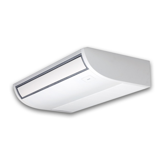
Unit Appearance and Dimensions
Details the physical dimensions and materials of the indoor unit main body.
Fan Unit Specifications
Specifies fan type, airflow, and motor power.
Indoor Unit Controller Specifications
Lists specifications for the included indoor unit controller.
Optional Controller Specifications
Lists specifications for separately sold controllers.
Refrigerant R32 and Pipe Material Guidelines
Refrigerant Pipe Material Requirements
Details requirements for copper pipe and joints used in refrigerant systems.
Required Tools for R32 Installation
R32 Exclusive Tools
Lists tools specifically required for R32 refrigerant system installation.
General Installation Tools
Lists general tools that can be used for installation, also applicable for R22.
Refrigerating Cycle Diagrams
Single Type Refrigerant Cycle Diagram
Illustrates the refrigerating cycle for a single indoor and outdoor unit combination.
Twin Type Refrigerant Cycle Diagram
Illustrates the refrigerating cycle for twin configurations with two indoor units.
Indoor Control Circuit Block Diagram
Wired Remote Controller Connection
Shows the connection diagram for a wired remote controller.
Control Specifications Overview
Power Reset Behavior
Describes how the unit behaves after a power supply reset.
Operation Mode Selection
Explains how to select operation modes like COOL, HEAT, DRY, AUTO.
Room Temperature Control Settings
Details the adjustment range for room temperature control.
Advanced Control Specifications
Automatic Capacity Control (GA Control)
Explains automatic capacity control based on temperature differences for various modes.
Automatic Cooling/Heating Control Logic
Details the logic for switching between cooling and heating operations.
Specialized Airflow Controls
Cool Air Discharge Prevention
Controls indoor fan based on temperature to prevent cool air discharge.
Freeze Prevention Control
Prevents freezing during cooling operation by adjusting fan speed.
Performance and Protection Features
High Temperature Release Control
Manages operation during high-temperature conditions to prevent issues.
Drain Pump Control (Optional)
Details the operation of the drain pump, including float switch interaction.
After-Heat Elimination
Manages indoor fan operation after heating stops to eliminate residual heat.
Advanced Control and Monitoring
HA Control Interface
Describes control via HA signal input, often for telecontrol systems.
Test Run Operation
Details how to perform a test run operation for troubleshooting or verification.
Filter Sign Display (Wired Remote)
Explains how the filter reset signal is sent and displayed on wired controllers.
System and Energy Management
Central Control Mode Selection
Allows selection of operating modes via a central controller.
Energy Saving Control Features
Enables energy-saving operations and adjusts settings for comfort.
Maximum Frequency Cut Control
Limits compressor frequency to prevent issues in specific conditions.
DC Motor Operation
Describes DC motor operation, including positioning and error detection.
Cleaning and Power Saving Modes
Self-Clean Operation (Dry Mode)
Details the self-clean operation performed after cooling/dry stops.
Power Saving Operation Details
Explains how to activate and configure power-saving modes.
Drain Pump Delay Operation
Describes the drain pump's operation after cooling stops to remove residual water.
Special Operation Modes
8°C Heating and Frost Protection
Provides low-temperature heating operation for frost protection.
Occupancy Sensor Operation
Details how the unit operates based on occupancy detection for energy saving.
Comfort and Draft Control
Soft Cooling Operation
Suppresses draft sensation by adjusting performance and louver angle.
Dual Set Point (AUTO Mode)
Allows separate temperature settings for heating and cooling in AUTO mode.
Fan Speed During Thermostat-OFF (Cooling)
Configures fan speed when the cooling mode is in thermostat-OFF state.
Draft Prevention Control
Prevents cold air downdraft during defrost by closing the louver.
System Communication and Redundancy
Communication Type Setting
Sets the communication type (TCC-Link/TU2C-Link) for indoor units and controllers.
Rotation and Backup Operation
Enables alternating operations and backup in case of system troubles.
Rotation, Backup, and Defrost Control
Defrost Shift Control
Adjusts defrost start times to prevent simultaneous operations and temperature drops.
Troubleshooting Summary (Wired Remote)
Pre-Troubleshooting Checks
Lists required tools and confirmation points before starting troubleshooting.
Troubleshooting Procedure Steps
Outlines the systematic procedure for diagnosing and resolving issues.
Troubleshooting Summary (Wireless Remote)
Pre-Troubleshooting Checks (Wireless)
Lists required tools and confirmation points before wireless troubleshooting.
Troubleshooting Procedure (Wireless)
Outlines the systematic procedure for wireless remote troubleshooting.
Troubleshooting Judgment Criteria
Troubleshooting Check Codes and Causes (Indoor Unit)
Lists indoor unit check codes, lamp indications, and their corresponding causes.
Indoor Unit Check Code Reference
Remote Controller Communication Troubles
Details check codes related to remote controller communication issues.
Central Control Device Communication Troubles
Lists check codes for central control system communication problems.
Indoor Unit Diagnostic Trouble Modes
Diagnostic Procedures and Measures
Provides step-by-step guidance and measures for diagnosing and resolving specific error codes.
Indoor Unit Check Code Diagnostic Flowcharts
E01 Trouble Diagnostic Flow
Flowchart for diagnosing and resolving E01 trouble codes.
E09 Trouble Diagnostic Flow
Flowchart for diagnosing and resolving E09 trouble codes.
Communication and Address Setup Errors
E18 Trouble Diagnostic Flow
Flowchart for diagnosing and resolving E18 communication trouble.
Group Control Address Errors (E08/L03/L07/L08)
Explains errors related to duplicated or unset group addresses.
L09 Trouble (Indoor Unit Capacity)
Addresses issues with setting the indoor unit capacity.
Central Controller and External Device Errors
L20 Trouble (Central Control Address)
Diagnoses issues related to duplicate central control system addresses.
L30 Trouble (External Device Operation)
Guides on checking external devices connected via the application control kit.
P30 Trouble (Central Controller Group Operation)
Addresses problems with central controller group operation and follower units.
Drain and Sensor Troubleshooting
P10 Trouble Diagnostic Flow (Drain System)
Flowchart for diagnosing drain pump and float switch problems.
F10 Trouble Diagnostic Flow (TA Sensor)
Flowchart for diagnosing TA sensor connection and resistance issues.
Valve, TC, and TCJ Sensor Troubleshooting
P19 Trouble Diagnostic Flow (4-Way Valve)
Guides on checking 4-way valve operation and replacing outdoor sensors.
F02 Trouble Diagnostic Flow (TC Sensor)
Flowchart for diagnosing TC sensor connection and resistance issues.
F01 Trouble Diagnostic Flow (TCJ Sensor)
Flowchart for diagnosing TCJ sensor connection and resistance issues.
Header, EEPROM, and Follower Unit Errors
E03 Trouble (Header Unit Communication)
Addresses loss of signal from remote/central controllers to the header unit.
F29 Trouble (EEPROM Error)
Indicates a detection trouble with the EEPROM on the indoor unit P.C. board.
P31 Trouble (Follower Unit Error)
Describes errors detected by follower units when header units have issues.
Service PC Board Replacement (Indoor Unit)
PC Board Replacement Procedures
Details the procedures for replacing the indoor unit PC board, including data backup.
Setting Data Reference Tables
Type Setting Table (CODE No. 10)
Details type settings (e.g., Ceiling Type) using CODE No. 10.
Indoor Unit Capacity Table (CODE No. 11)
Lists indoor unit capacities corresponding to CODE No. 11.
Test Run Overview and Forced Defrost
Forced Defrost Setup (Wired Remote)
Procedure to set up forced defrost operation using the wired remote controller.
PC Board LED Indicator Guide
Explains the meaning of various LEDs on the indoor unit's PC board.
Remote Controller Wiring and Settings
Dual Remote Controller Operation
Details how to operate units with two remote controllers.
Setting Remote Controller as Follower
Explains how to configure a remote controller as a follower unit.
Trouble History Monitoring and Group Operation
Group Control Requirements
Specifies requirements for group control operation, including power and wiring.
Group Control Operation Overview
Explains how group operation of up to 16 units is controlled by a remote controller.
Group Control System Example
Provides an example of system configuration for group control.
1:1 Model Connection Interface Setup
1:1 Model Connection Interface Function
Explains the purpose of the optional PC board for 1:1 model connection.
1:1 Model Interface Block Diagram
Shows the block diagram of the 1:1 model connection interface.
1:1 Model Interface Wiring Connection
Provides wiring instructions for the 1:1 model connection interface.
Wiring Specifications and SW01 Setup
Central Control System Wiring Specifications
Details wiring specifications for central control systems, including wire types and lengths.
PC Board Switch (SW01) Setup
Instructions for setting up the terminator using SW01 on the PC board.
Address Setup Procedures
Central Control Address Setup Requirement
Notes the necessity of setting central control addresses and indoor unit numbers.
Setting Central Control Address Number
Details how to set the central control address number from the indoor unit side.
Address Setup Process
Address Setup Procedure Steps
Outlines the procedure for automatic and manual address setup for indoor units.
Address Setup and Group Control Terminology
Group Control Terminology Definitions
Defines terms like Indoor unit No., Group address, Header unit, Follower unit, Master/Sub unit.
System Configuration Examples
Illustrates single and twin system configurations for address setup.
Group Operation Configurations
Single Group Operation
Explains how each indoor unit controls the outdoor unit individually in single group operation.
Manual Address Setting for Multiple Groups
Details manual address setting for master and sub units in multiple group operations.
Manual Address Setup (Wired Remote)
Manual Line Address Setup
Step-by-step guide to manually set the line address using the remote controller.
Manual Indoor Unit Address Setup
Step-by-step guide to manually set the indoor unit address.
Manual Group Address Setup
Step-by-step guide to manually set the group address for indoor units.
Detachments: Air Intake Grille and Electric Parts Box
Air Intake Grille Detachment and Attachment
Detailed instructions for removing and attaching the air intake grille.
Electric Parts Box Cover Removal
Instructions for detaching and attaching the electric parts box cover.
Detachments: Electric Parts Box and Control PC Board
Electric Parts Box Detachment
Instructions for removing the electric parts box.
Control PC Board Detachment
Instructions for removing the control PC board and its connectors.
Detachments: Fan, Fan Case, and Shaft
Fan, Fan Case, and Shaft Detachment
Detailed steps for removing the fan, fan case, and shaft.
Warnings on Refrigerant Leakage
Refrigerant Concentration Limit Check
Details the acceptable refrigerant concentration limits in rooms and required countermeasures.
Need help?
Do you have a question about the RAV-HM1101CTP Series and is the answer not in the manual?
Questions and answers