Table of Contents
Advertisement
Quick Links
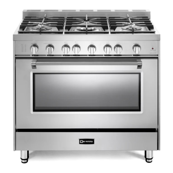
SINGLE OVEN GAS RANGE
VPFSGG365..
Models:
INSTALLATION INSTRUCTIONS
IMPORTANT - PLEASE READ AND FOLLOW
•
Before beginning, please read these instructions completely and carefully.
•
Do not remove permanently affixed labels, warnings, or plates from the product. This may
void the warranty.
•
Please observe all local and national codes and ordinances.
•
Please ensure that this product is properly grounded.
The installer should leave these instructions with the consumer who should retain
•
for local inspector's use and for future reference.
The electrical plug should always be accessible.
•
Installation must conform with local codes or in the absence of codes, the National Fuel Gas
Code ANSI Z223.1/NFPA 54 - Iatest edition. Electrical installation must be in accordance
with the National Electrical Code, ANSI/NFPA70 - latest edition and/or local codes. IN
CANADA: Installation must be in accordance with the current CAN/CGA-B149.1 National
Gas Installation Code or CAN/CGA-B149.2, Propane Installation Code and/or local codes.
Electrical installation must be in accordance with the current CSA C22.1 Canadian Electrical
Codes Part 1 and/or local codes.
INSTALLATION IN MANUFACTURED (MOBILE) HOME: The installation must conform
with the Manufactured Home Construction and Safety Standard, Title 24 CFR, Part 3280
[formerly the Federal Standard for Mobile Home Construction and Safety, Title 24, HUD
(Part 280)] or, when such standard is not applicable, the Standard for Manufactured Home
Installations, ANSI/NCSBCS A225.1, or with local codes where applicable.
INSTALLATION IN RECREATIONAL PARK TRAILERS: The installation must conform with
state or other codes or, in the absence of such codes, with the Standard for Recreational
Park Trailers, ANSI A119.5.
Installation of any gas-fired equipment should be made by a Iicensed plumber. A manual
shut-off valve must be installed in an accessible location in the gas line external to the
appliance for the purpose of turning on or shutting off gas to the appliance (In Massachusetts
such shutoff devices should be approved by the Board of State Examiners of Plumbers &
Gas Fitters).
If an external electrical source is utilized, the appliance, when installed, must be electrically
grounded in accordance with local codes or, in the absence of local codes, with the national
Electrical Code, ANSI/NFPA 70.
Some models are supplied with a protective film on steel and aluminium
parts. This film must be removed before installing/using the appliance.
THIS RANGE IS FOR RESIDENTIAL USE ONLY
FOR INSTALLER ONLY
Advertisement
Table of Contents

Related Manuals for Verona VPFSGG365SS


Summarization of Contents
Installation Instructions
Important - Please Read and Follow
Crucial initial steps, warnings, and general installation guidelines.
Installation in Manufactured (Mobile) Homes
Conforms to specific standards like Title 24 CFR, Part 3280 for mobile home installation.
Installation in Recreational Park Trailers
Conforms to ANSI A119.5 standard or state/local codes for park trailers.
Tools Needed for Installation
Lists necessary tools like screwdrivers, wrenches, hammers, drills, and safety gloves.
General Information
Installation Requirements and Codes
Adherence to national, local, fuel gas, and electrical codes.
Safety and Usage Precautions
Precautions against space heating, fire risks, and misuse of oven doors.
Electrical Grounding Instructions
Instructions for safe electrical grounding and connection per NEC.
Replacement Parts
Information on obtaining authorized replacement parts from distributors.
Proximity to Side Cabinets
Range Dimensions and Backguard
Details range dimensions and highlights the mandatory backguard installation.
Cabinet Clearance Requirements
Specifies required minimum clearances for side and wall cabinets.
Gas and Electric Connection
Gas Connection Specifications
Diagrams and dimensions for gas connection points.
Electrical Connection Specifications
Diagrams and dimensions for electrical connection points.
Fitting the Adjustable Feet and Moving the Cooker
Fitting the Adjustable Feet
Instructions for fitting adjustable feet and leveling the cooker.
Moving the Cooker
Guidelines for safely moving the cooker, emphasizing two-person lifts.
Assembling the Backguard
Backguard Assembly Instructions
Step-by-step guide for assembling and attaching the backguard.
Installing the Anti-Tip Bracket
Anti-Tip Bracket Components
Identifies the two components: adjustable bracket and stability bracket.
Bracket Installation Procedure
Details threading the bolt, fixing the adjustable bracket, and ensuring proper fitting.
Installing the Cooktop Front Guard
Cooktop Front Guard Installation
Instructions for installing the front guard, requiring cooktop disassembly.
Gas Connection
Manual Shut-off Valve
Requirement for an accessible manual shut-off valve in the gas line.
Pressure Regulator Installation
Instructions for installing the pressure regulator for safe gas supply.
Gas Connection Specification
Gas Piping Diagram
Detailed piping diagram and specifications for gas connections.
Testing and Connections
Gas Supply Piping Test Points
Details using a test point adapter to check manifold pressure.
Flexible and Rigid Pipe Connections
Recommends flexible connectors and proper methods for rigid pipe connections.
Leak Testing Procedure
Method for testing gas connections for leaks using soapy water.
Conversion to LP/Propane Gas
LP/Propane Gas Conversion
Steps for converting to LP/Propane gas, including injector changes.
Setting the Pressure Regulator
Procedure for accessing and reversing the pressure regulator for gas conversion.
Burner Adjustments and Injector Replacement
Burner Injectors Table
Table listing injector sizes for different burners and gas types.
Injector Substitution Operations
Steps for replacing injectors on different burner types.
Setting the Burner Minimum
Triple-ring and Semirapid Burner Minimum
Adjusting the regulation screw R1 for minimum flame on specific burners.
Dual Burner Minimum Adjustment
Adjusting screws R2 and R3 for minimum flame on dual burners.
Oven and Broil Burner Injector Replacement
Oven Burner Injector Replacement
Procedure for replacing injectors on the oven burner.
Broil Burner Injector Replacement
Steps for replacing the injector on the broil burner.
Adjustment of the Oven Burner Minimum
Oven Burner Minimum Flame Setting
Fine-tuning the oven burner minimum flame using the by-pass screw.
Electrical Connection
Electrical Supply and Grounding
Requirements for electrical supply voltage, amperage, and grounding.
Wiring Diagram Overview
Explanation of the electrical wiring diagram and its components.
Need help?
Do you have a question about the VPFSGG365SS and is the answer not in the manual?
Questions and answers