Table of Contents
Advertisement
Quick Links
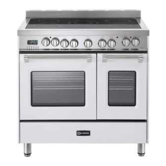
ELECTRIC RANGE
for residential use only
VPFSEE365D..
Models:
INSTALLATION INSTRUCTIONS
IMPORTANT - PLEASE READ AND FOLLOW
•
Before beginning, please read these instructions completely and carefully.
Do not remove permanently affixed labels, warnings, or plates from the product. This may
•
void the warranty.
•
Please observe all local and national codes and ordinances.
•
Please ensure that this product is properly grounded.
•
The installer should leave these instructions with the consumer who should retain
for local inspector's use and for future reference.
Electrical installation must be in accordance with the National Electrical Code, ANSI/NFPA70
- latest edition and/or local codes.
IN CANADA: Electrical installation must be in accordance with the current CSA C22.1
Canadian Electrical Codes Part 1 and/or local codes.
Some models are supplied with a protective film on steel and aluminium
parts. This film must be removed before installing/using the appliance.
THIS RANGE IS FOR RESIDENTIAL USE ONLY
FOR INSTALLER ONLY
R
Advertisement
Table of Contents

Subscribe to Our Youtube Channel
Related Manuals for Verona VPFSEE365DW


Summary of Contents for Verona VPFSEE365DW
- Page 1 ELECTRIC RANGE for residential use only VPFSEE365D.. Models: INSTALLATION INSTRUCTIONS IMPORTANT - PLEASE READ AND FOLLOW • Before beginning, please read these instructions completely and carefully. Do not remove permanently affixed labels, warnings, or plates from the product. This may •...
- Page 3 WARNING Tip-Over Hazard A child or adult can tip the range and be killed. Install anti-tip device to range and/or structure per installation instructions. Engage the range to the anti-tip device Installed to the structure. Re-engage anti-tip device if range is moved. Failure to follow these instructions can result in death or serious burns to children and adults.
-
Page 4: Installation Instructions
INSTALLATION INSTRUCTIONS WARNING! THIS APPLIANCE MUST BE INSTALLED BY A QUALIFIED INSTALLER. Installation must conform with local codes. Improper installation, adjustment, alteration, services, or maintenance can cause injury or property damage. Consult a qualified installer or a service agent. IMPORTANT: The use of suitable protective clothing/gloves is recommended when handling, installing of this appliance. -
Page 5: General Information
GENERAL INFORMATION WARNING!! WARNING!! ELECTRICAL GROUNDING INSTRUCTIONS This appliance shall not be used for space heating. This The range must be electrically grounded in accordance with information is based on safety considerations. local codes or, in the absence of local codes, with the National Electrical Code, ANSI/NFPA No. - Page 6 installation PROXIMITY TO SIDE CABINETS 2. The range CANNOT be installed directly adjacent to sidewalls, 1. This range may be installed directly adjacent to existing 36" (914 mm) high base cabinets. tall cabinets, tall appliances, or other side vertical surfaces above 36”...
-
Page 7: Electric Connection
ELECTRIC CONNECTION Dotted line showing the position of the range when installed Area for ELECTRICAL connection 5” 1/8 ÷ 7” 3/32 (130÷180 mm) [depending on feet regulation] Fig. 1.2... - Page 8 ( 3 3 0 m m ) 1 3 " m a x . PROXIMITY TO SIDE CABINETS RANGE WITH 8" BACKGUARD Fig. 1.3a 1 3 " m a x . ( 3 3 0 m m ) Fig. 1.3b...
- Page 9 1 3 " m a x . ( 3 3 0 m m ) PROXIMITY TO SIDE CABINETS RANGE WITH 3" BACKGUARD Fig. 1.3c ( 3 3 0 m m ) 1 3 " m a x . Fig. 1.3d...
-
Page 10: Fitting The Adjustable Feet
Fig. 1.5 Fig. 1.4 FITTING THE ADJUSTABLE FEET The adjustable feet must be fitted to the base of the cooker before use. Rest the rear of the cooker on a piece of the polystyrene packaging exposing the base for the fitting of the feet. ATTENTION: Most important! Pay special attention not to damage the range dur- ing this operation. -
Page 11: Assembling The Backguard
ASSEMBLING THE BACKGUARD It is mandatory to install the backguard IMPORTANT: THE BACKGUARD IS NOT PACKAGED WITH THE APPLIANCE BUT IT IS SUPPLIED SEPARATELY BY THE DISTRIBUTOR. Assemble the backguard as shown in figure • WITH RESPECT TO THE FIGURES BELOW, ONE ADDITIONAL 1.8 or 1.9 and fix it by screwing the 5 screws BACKGUARD (HEIGHT = 4”... -
Page 12: Installing The Anti-Tip Bracket
INSTALLING THE ANTI-TIP BRACKET The anti-tip bracket has two components: the adjustable bracket • the stability bracket • IMPORTANT! You must install both parts of the anti-tip bracket and ensure they are properly fitted together to prevent the range from tipping. To fit the anti-tip bracket Fig. - Page 13 Fix the stability bracket in place. It can be WARNING fixed as follows: To the floor OR on the rear wall by #4 Tip-Over Hazard • screws (supplied). A child or adult can tip the range and be killed. To the floor AND on the rear wall by #8 •...
-
Page 14: Electrical Requirements
electrical connection ELECTRICAL REQUIREMENTS • This appliance must be properly installed and grounded by a qualified technician in WARNING accordance with the National Electrical Code ANSI/NFPA No.70 (latest edition) and local electrical code requirements. IN CANADA: Electrical installation must be in accordance with the current CSA C22.1 Canadian Electrical Codes Part1 and/or local TO AVOID ELECTRICAL SHOCK codes. - Page 15 3-Wire Power Cord Installation Fig. 2.1 (See Figures 2.1, 2.2 and 2.3) 1. Remove the Terminal Block Access Plate on the back of the range by unscrewing the 6 fixing Screws (fig. 2.1). 2. Insert the Power Cord through the hole in the Power Cord Bracket;...
- Page 16 Fig. 2.5 3-Wire Conduit Installation (See Figures 2.1, 2.5 and 2.6) 1. Remove the Terminal Block Access Plate on the back of the range by unscrewing the 6 fixing Screws (fig. 2.1). 2. Feed 3/4" trade size Conduit through the hole in the Conduit Bracket and secure to the Conduit Bracket with a Conduit Clamp.
-
Page 17: Wiring Diagram
WIRING DIAGRAM RIGHT OVEN LEFT OVEN Pilot Pilot Pilot Pilot CIR1 TL-CF TL-CF ELECTRIC DIAGRAM KEY Cooling fan motor LEFT OVEN RIGHT OVEN GLASS CERAMIC HOB TL-CF Cooling fan thermal overload Oven switch Oven switch F2/3/5/6 Single zones energy regulators Air switch Oven thermostat Oven thermostat... - Page 20 The manufacturer cannot be held responsible for possible inaccuracies due to printing or transcription errors in the present booklet. The manufacturer reserves the right to make all modifications to its products deemed necessary for manufacture or commercial reasons at any moment and without prior notice, without jeopardising the essential functional and safety characteristics of the appliances.
Need help?
Do you have a question about the VPFSEE365DW and is the answer not in the manual?
Questions and answers