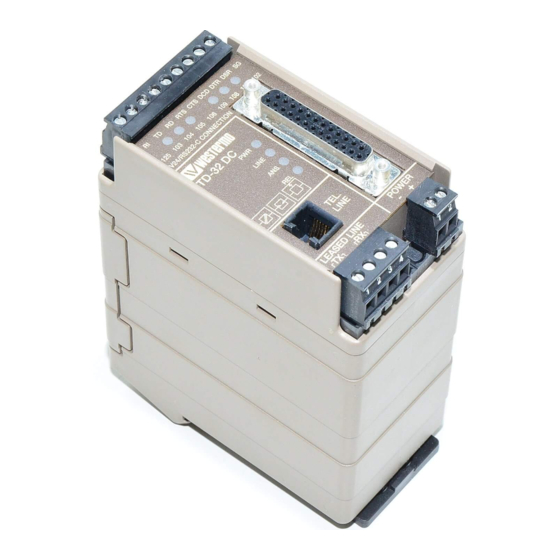
Summarization of Contents
Connections
RS-232/V.24 Connections
Pinouts for the 25-pole D-sub and 9-pole screw terminal.
Line Connection
How to connect the telephone line via the RJ-12 or 4-pole screw block.
Line Configurations
Typical TD-32 Line Connections
Diagrams illustrating leased line and dial-up connections.
Handshaking
Explanation of RTS-CTS and AT&K0 settings for handshake.
DIP Switch Configuration
Switch I Settings
Configuration for standard dial-up and leased line modes.
Switch 2 Settings
Settings for communication mode and synchronous clock source.
Switch 3 Settings
Settings for line connection type and flow control.
Switch 4 Settings
Configuration for serial speed and data format.
Switch 5 Settings
Configuration for line modulation.
Status Indicators
LED Status Indicators
Meaning of PWR, LINE, ANS, REL, TD, RD, RTS, DCD, DSR LEDs.
AT Command Reference
DTE Command Line Syntax
Rules and syntax for issuing AT commands to the modem.
Dialing & Connection Commands
Commands for initiating calls and managing line connections.
Configuration & Control Commands
Commands for factory reset, guard tone, and flow control.
Test & Diagnostics Commands
Commands for performing diagnostic tests on the modem.
S-register Configuration
Basic S-registers (S0-S8)
Settings for auto-answer, timing, and characters.
S14 General Bit Mapped Options
Controls echo, result codes, and tone/pulse dialing.
S16 Test Timer & Sync Options
Settings for test duration and auto-sync configurations.
S21-S22 Mode & Control Options
Settings for speaker, DSR, receiver disconnect, and speaker control.


Need help?
Do you have a question about the TD-32 AC EU and is the answer not in the manual?
Questions and answers