
Related Manuals for Ingenic X2000


Summarization of Contents
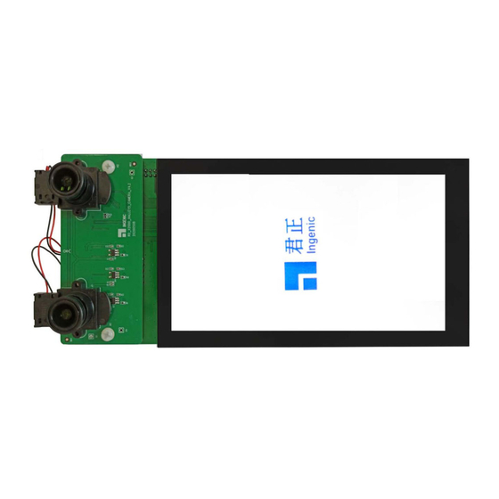
Overview
Hardware Configuration
Details the modules comprising the Halley5 development kit, including core, base, LCD, and camera boards.
Functional Block Diagram
Presents a block diagram illustrating the functional connections and components of the Halley5 development kit.
Halley5 Core Board
Main Components of the Core Board
Outlines the primary components of the Halley5 core board, including processor, memory, and wireless modules.
Power Circuit
Describes the power supply circuit for the Halley5 core board, including PMIC and LDO functions.
WIFI & BT Function Circuit
Explains the Wi-Fi and Bluetooth module integration and circuit design on the core board.
SPI Flash Function Circuit
Details the circuit for the SPI NAND Flash storage component on the core board.
Halley5 Base Board
Configurations of the Halley5 Base Board
Lists the various ports and connectors available on the Halley5 base board for peripherals.
USB OTG Function Circuit
Describes the USB OTG functionality and circuit connections on the Halley5 base board.
DEBUG Function Circuit
Explains the USB to UART circuit used for debugging and serial communication.
SD Card Function Circuit
Details the Micro SD card interface and its circuit on the base board.
AMIC Function Circuit
Describes the Analog Microphone (AMIC) input circuit on the base board.
DMIC
Explains the Digital Microphone (DMIC) port and its support on the base board.
SPEAKER Function Circuit
Details the circuit for audio output through the speaker, including the CODEC.
Keys Function Circuit
Describes the function and circuit of the various keys on the base board for user input.
LED Function Circuit
Explains the circuit for system power and reset LEDs on the base board.
OLED Function Circuit
Details the circuit for driving the OLED display, including touch panel support.
CAMERA Interface
Describes the MIPI and DVP camera interface for connecting external camera modules.
Ethernet interface
Explains the built-in Ethernet MAC controller and PHY for network connectivity.
Expansion Interface
Details the expansion port providing UART, SPI, ADC, and PWM signals.
Quick Start the Halley5 Development Kit
Connecting the Hardware
Provides instructions on connecting power and debug interfaces to the development kit.
System Boot
Explains the automatic boot process from SPI NAND Flash upon power-up or reset.
Firmware Downloading
Guides on how to connect the board to a PC for firmware downloading via USB.
Need help?
Do you have a question about the X2000 and is the answer not in the manual?
Questions and answers