Table of Contents
Advertisement
Quick Links
Advertisement
Chapters
Table of Contents

Related Manuals for Anritsu MS8609A


Summarization of Contents
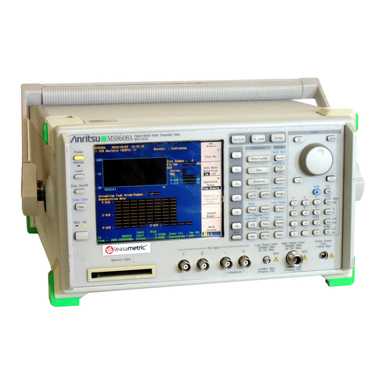
MS8608A/MS8609A Digital Mobile Radio Transmitter Tester Operation Manual Vol. 1 (Main Unit)
17th Edition
Specifies the edition of the operation manual.
Safety Symbols
Symbols used in manual
Explains symbols used within the manual text to denote hazards.
Safety Symbols Used on Equipment and in Manual
Describes safety symbols found on the equipment and within the manual.
For Safety
WARNING
Provides critical warnings regarding safe operation, manual consultation, and electrical shock hazards.
Electric Shock
Details precautions to prevent electric shock, emphasizing proper grounding.
Repair
Advises against operator repair and specifies qualified personnel for servicing.
Falling Over
Discusses proper equipment positioning to prevent instability and damage from falling.
Battery Fluid
Warns about hazardous battery fluid and provides handling instructions in case of exposure.
LCD
Advises against mechanical shock to the LCD and warns about potential liquid leakage.
CAUTION
Provides cautions related to fuse replacement, dust accumulation, and input signal limits.
Replacing Memory Back-up Battery
Details battery replacement by service personnel and its limited lifespan.
External Storage Media
Advises on handling memory cards and backing up data due to potential loss.
Use in a residential environment
Notes potential radio interference in residential settings and user responsibility for mitigation.
Equipment Certificate
Anritsu Warranty
Outlines warranty conditions, voiding factors, and liability limitations.
Anritsu Corporation Contact
Provides instructions for contacting Anritsu Service and Sales offices for malfunctions.
CE Conformity Marking
Authorized representative
Lists the authorized representative in Europe for CE conformity.
Caution for the operation with Option 05 installed
Transport condition
Provides instructions for transporting the unit, including using a carrying case and power-off duration.
Operating condition
Advises against placing magnetic objects near the unit due to frequency variations.
Section 1 General
Product Outline
Outlines the MS8608A/MS8609A as a measuring device for digital mobile communications and its spectrum analyzer function.
Equipment Configuration
Describes the standard configuration of the MS8608A/MS8609A, including main unit and accessories.
Options
Lists and describes available optional accessories for the MS8608A/MS8609A, sold separately.
Measurement software
Details optional measurement software available for evaluating W-CDMA and GSM/EDGE terminals.
Optional Accessories and Peripherals
Lists optional accessories and peripherals available for purchase for the MS8608A/MS8609A.
Specifications
Provides detailed specifications for the MS8608A/MS8609A main unit, including frequency range, input levels, and connectors.
Section 2 Preparations Before Use
Installation Site and Environmental Conditions
Details recommended operating temperatures, humidity, and locations to avoid for optimal performance.
Safety Measures
Outlines safety procedures to prevent electric shock, equipment damage, and operational interruptions.
Power-on
Explains pre-power-on checks for grounding and voltage, and precautions during power-on.
Input level to RF Input
Warns against exceeding specified input power levels to prevent damage to RF input circuits.
Caution of handling the RF Input Connector
Advises using correct connector types (N-type and SMA) for RF inputs to prevent accidental damage.
Installation
Provides guidance on installing the unit, including rack mounting and oscillator connections.
Preparations Before Power-on
Lists necessary procedures before supplying power to prevent issues like electric shock and voltage damage.
Connecting the Power Cord
Provides instructions for connecting the power cord, emphasizing the use of a 3-pin grounded plug.
Replacing fuse
Details safety precautions and procedures for replacing fuses, warning against fire risks from incorrect ratings.
Precaution for Handling Memory Card
Advises on proper handling of memory cards to prevent data loss and damage from static electricity.
Section 3 Panel Description
Table of Front and Rear Panel Features
Lists and explains the functions of front and rear panel markings and keys.
Section 4 Basic Operation Procedure
Signal Display
Guides on turning on the power and basic signal display operations in the spectrum analyzer mode.
Turn the power on
Explains the procedure for turning the unit on and off, emphasizing the one-second press requirement.
Move to spectrum analyzer mode
Details how to switch the mode to spectrum analyzer and perform partial resettings.
Execute automatic calibration
Describes the process of performing automatic calibration after warm-up using an internal source.
Set the signal to the center of the screen
Explains how to set the center frequency using the frequency, span, and amplitude keys.
Enlarge and display the signal
Guides on using the span key to enlarge the signal display for better viewing.
Marker Operation
Explains how to use markers to check signal frequency and level, including zone marker and marker-to-CF functions.
“Measure” Function Check
Details how to perform measurements like frequency count and C/N ratio using the Measure key.
Shifting of result position
Describes how to select the displayed position for measurement results from four patterns.
Section 5 Setting Functions
Setting Operation Status
Explains basic configuration settings like display title, date, time, and brightness on the Config screen.
Setting Title (Display)
Guides on setting the title area, including comment, clock, and date format options.
Setting Connection to External Monitor (CRT)
Details how to enable or disable the RGB output for an external monitor.
Adjusting LCD Brightness (LCD BRIGHTNESS)
Explains how to adjust the brightness level of the LCD display.
Setting Alarm Sound On/Off (Buzzer)
Describes how to enable or disable the buzzer for alarms and invalid value settings.
Setting Window Cursor Operation Mode (Window Cursor Mode)
Explains how to set the cursor movement mode in windows to TURN or STOP.
Setting Date and Time
Guides on setting the internal date and time of the MS8608A/MS8609A.
Setting Start-up Screen (Screen)
Describes how to configure the screen that appears upon power-on (Spectrum, System, or Last).
Setting Initial State (Initial)
Explains how to set the initial state after power-on to 'Before Power Off' or 'Fixed State'.
Setting Copy Destination (Copy to )
Details how to set the destination for copying data, either to a printer or memory card.
Setting Printer Type (Printer setup)
Guides on selecting the printer type for outputting BMP files.
Setting Type of BMP File (BMP file setup)
Describes how to set the BMP file type to color or monochrome for output.
Setting Print Destination
Explains how to set printer control, type, and BMP file output destination.
Setting External Interface
Details how to perform settings for external interfaces like GPIB, RS-232C, and Ethernet.
Selecting interface to be used (Connect To Controller)
Guides on selecting the interface (GPIB, RS-232C, Ethernet) for connecting to an external controller.
Setting GPIB Address (My Address)
Explains how to set the GPIB address for communication with the controller.
Setting RS-232C (RS-232C)
Details the settings for RS-232C communication, including baud rate, parity, and data bits.
Setting Ethernet
Explains how to configure Ethernet settings such as IP address, net mask, and gateway.
File Operations
Covers operations related to files on the memory card, including opening, selecting, and deleting.
Selecting File
Guides on selecting files from the memory card, including changing directories.
Deleting File
Describes the procedure for deleting files from the memory card, with a warning about irreversibility.
Write-Protecting Files
Explains how to write-protect files on the memory card to prevent changes or deletion.
Formatting Memory Card
Details the process of formatting the memory card, warning that it erases all data.
Changing Measurement System
Explains how to switch measurement systems when multiple software packages are installed in Transmitter Tester mode.
Moving to Transmitter Tester Mode
Guides on switching the operating mode to Transmitter Tester mode.
Moving to Spectrum Analyzer Mode
Guides on switching the operating mode to Spectrum Analyzer mode.
Installing Measurement Software
Details the procedure for installing measurement software onto the MS8608A/MS8609A.
Installing Core Module Software
Explains how to install new core module software onto the MS8608A/MS8609A.
Displaying Maintenance Parameter Information
Describes how to display maintenance parameters like live timer counts and switch usage.
Registering Installation Key
Details the process of registering installation keys for new measurement software.
Initialization (Restore shipment state)
Explains how to initialize parameters and waveform data to their shipment state.
Section 6 Performance Tests
Requirement for Performance Tests
Explains the purpose and schedule for performing performance tests as preventive maintenance.
Instruments Required for Performance Test
Lists the necessary instruments and their required specifications for conducting performance tests.
Reference oscillator frequency stability
Describes the procedure and specifications for testing the stability of the 10 MHz reference oscillator.
Rubidium reference oscillator frequency stability (Option 05)
Details the testing procedure and specifications for the Rubidium reference oscillator's frequency stability.
Frequency readout accuracy
Explains how to test and verify the accuracy of frequency readings using a synthesized signal generator.
Frequency span readout accuracy
Describes the procedure to test frequency span accuracy by measuring peak levels at screen divisions.
Resolution bandwidth (RBW) and selectivity
Explains resolution bandwidth and selectivity, and how to test them using a signal generator.
Sideband phase noise
Describes how to measure sideband phase noise by comparing noise level to peak signal.
Frequency measurement accuracy
Guides on testing frequency measurement accuracy using a built-in counter and signal generator.
Amplitude display linearity
Explains how to test the error per vertical graduation for the LOG display linearity.
Frequency response
Details the procedure for testing frequency response by inputting signals of different frequencies.
Reference level accuracy
Describes how to test absolute amplitude level accuracy after inputting a calibrated SG output.
Average noise level
Explains how to measure the average noise level by distributing internal noise across the frequency band.
Second harmonic distortion
Describes how to test second harmonic distortion generated by analyzer non-linearity.
Resolution bandwidth (RBW) switching uncertainty
Explains how to measure level error at peak point when RBW is switched.
Input attenuator (RF ATT) switching uncertainty
Details how to measure switching error when the RF input attenuation is switched.
Frequency domain sweep time accuracy
Explains how to test frequency domain sweep time accuracy.
Time domain sweep time accuracy
Describes how to test time domain sweep time accuracy.
Service
Provides information on contacting Anritsu for repair services and required details.
Section 7 Storage and Transportation
Cleaning Cabinet
Provides instructions for cleaning the external cabinet of the unit.
Storage Precautions
Details precautions for long-term storage, including environmental conditions and avoiding sunlight.
Repacking and Transportation
Provides precautions for repacking and transporting the unit for servicing.
Appendixes
Appendix A Front and Rear Panel Layout
Shows diagrams illustrating the front and rear panel layouts of the MS8608A and MS8609A.
Appendix B Block Diagram
Presents the block diagram illustrating the internal structure of the MS8608A.
Appendix C Performance Test Record
Provides a template for recording performance test results.
SECTION 1 GENERAL
General
Outlines remote control capabilities and system upgrade examples using various interfaces.
Remote control functions
Lists functions available for remote control, including parameter control and setting.
Interface port selection functions
Explains how to select interface ports (RS-232C, GPIB, Ethernet, Parallel) for external connections.
Examples of system upgrades using various interfaces
Illustrates system configurations for stand-alone operation and host computer control.
Specifications of RS-232C
Lists the standard specifications for the RS-232C interface, including baud rate and data bits.
Specifications of GPIB
Lists the standard specifications and supplementary explanations for the GPIB interface.
SECTION 2 CONNECTING DEVICE
Connecting an external device with an RS-232C cable
Guides on connecting external devices using an RS-232C cable, including cable details.
Connection diagram of RS-232C interface signals
Shows the signal connections for RS-232C interface between the MS8608A/MS8609A and a PC.
Setting the connection port interfaces
Refers to Section 5 for setting the external interface connection ports.
Setting the RS-232C interface conditions
Advises setting RS-232C conditions to match the external device.
Connecting a device with a GPIB cable
Guides on connecting devices using a GPIB cable, including connection notes and system limits.
Setting the GPIB address
Refers to Section 5 for setting the GPIB address.
SECTION 3 DEVICE MESSAGE FORMAT
General description
Describes device messages, program messages, and response messages for controller-device communication.
Program message format
Defines the formats for program messages, including message units, headers, and data types.
Response message format
Defines the formats for response messages, including message terminators and data types.
SECTION 4 STATUS STRUCTURE
IEEE488.2 Standard Status Model
Illustrates the standard model for data structures and status reporting defined by IEEE488.2.
Status Byte (STB) Register
Explains the STB register, ESB, and MAV summary messages used for status reporting.
Device-dependent summary messages
Details which bits are used in the status byte register and the role of bit 2.
Reading and clearing the STB register
Describes methods for reading and clearing the STB register using serial polling or common queries.
Service Request (SRQ) Enabling Operation
Explains how bits in the SRE register determine which STB bits can generate SRQ.
Standard Event Status Register
Defines the bit names and descriptions for standard events within the Standard Event Status Register.
Reading, writing, and clearing the Standard Event Status Register
Details how to read, write, and clear the Standard Event Status Register.
Reading, writing, and clearing the Standard Event Status Enable Register
Explains how to read, write, and clear the Standard Event Status Enable Register.
Extended Event Status Register
Describes the Extended Event Status Register, including unused bits and the assignment of bit 2.
Bit definition of END Event Status Register
Defines the bit names and descriptions for events in the END Event Status Register.
Reading, writing, and clearing the Extended Event Status Register
Details how to read, write, and clear the Extended Event Status Register.
Reading, writing, and clearing the Extended Status Enable Register
Explains how to read, write, and clear the Extended Status Enable Register.
Techniques for Synchronizing MS8608A/MS8609A with a Controller
Describes methods for synchronizing the instrument with a controller, such as waiting for ∗OPC? or SRQ.
Wait for a response after the ∗OPC? query is sent
Explains the process of synchronizing by waiting for the ∗OPC? query response.
Wait for a service request after ∗OPC is sent (only when the GPIB interface bus is used)
Details synchronization using SRQ after the ∗OPC command, applicable for GPIB interface.
SECTION 5 INITIAL SETTINGS
Bus Initialization using the IFC Statement
Explains how the IFC statement initializes all interface functions connected to the GPIB bus.
Initialization for Message Exchange by DCL and SDC Bus Commands
Describes initialization for message exchange using DCL and SDC commands, detailing affected items.
Device Initialization using the ∗RST Command
Explains the ∗RST command for resetting the device to a specific initial state.
Device Initialization using the INI/IP Command
Details the INI and IP commands for initializing the device at level 3.
Device Status at Power-on
Describes the device status and cleared items when the power is turned on.
SECTION 6 TABLES OF DEVICE MESSAGES
How to Read the Command List
Explains how to interpret arguments, types, and units in the command list.
Program Messages and Query Messages
Lists arguments, meanings, types, and unit/suffix codes for program and query messages.
Response Messages
Lists arguments, meanings, types, and units for response messages.
Command List
Provides a comprehensive list of commands, their program, query, and response messages, and remarks.
SECTION 7 DETAILED DESCRIPTION OF COMMANDS
How To Read Detailed Command Description on Measurement Screen
Explains how to interpret command descriptions, including syntax, function, values, restrictions, and examples.
∗CLS
Describes the ∗CLS command for performing zero-clear of the standard event-status byte register.
∗ESE
Details the ∗ESE command for setting or clearing the standard event status enable register.
∗ESR
Explains the ∗ESR command for reading the standard event status register.
∗IDN
Describes the ∗IDN command for reading product information like model name and serial number.
∗OPC
Explains the ∗OPC command for setting the operation-complete bit when a device operation is finished.
∗RST
Details the ∗RST command for resetting the device to its initial state.
∗SRE
Explains the ∗SRE command for setting the bits of the service request enable register.
∗STB
Describes the ∗STB command for reading the status byte that contains the MSS bit.
∗TRG
Explains the ∗TRG command for executing a single sweep.
∗TST
Details the ∗TST command for executing internal self-test and returning error presence.
∗WAI
Explains the ∗WAI command to make the next command wait while the device is executing a command.
ALARM
Describes the ALARM command for setting the buzzer to sound on errors or other times.
BAUD
Explains the BAUD command for setting the communication speed for RS-232C.
BEP
Details the BEP command for setting the buzzer operation, similar to ALARM.
BIN
Describes the BIN command for setting the waveform data output format to ASCII or binary.
BRIGHT
Explains the BRIGHT command for setting the LCD display brightness.
COLORPTN
Details the COLORPTN command for setting the screen color pattern.
COMMENT
Explains the COMMENT command for setting the title and clock display on the screen.
COPYCOLOR
Describes the COPYCOLOR command for selecting the base color pattern for user definition.
CURSORMODE
Explains the CURSORMODE command for setting the cursor movement mode in windows.
DATB
Details the DATB command for setting the data length of the RS-232C communication port.
DATE
Guides on setting the date (year, month, day) using the DATE command.
DATEMODE
Explains the DATEMODE command for setting the date display format.
DELM
Details the DELM command for setting the type of terminator for RS-232C messages.
DISPLAY
Explains the DISPLAY command for turning the LCD display power On/Off.
ESE2
Explains the ESE2 command for selecting bits in the END event status enable register.
FLWCTRL
Details the FLWCTRL command for setting XON/XOFF flow control for RS-232C.
GATEWAY
Explains the GATEWAY command for setting the Ethernet gateway address.
HOLD
Describes the HOLD command for deleting the currently displayed error message.
HOSTADRS
Explains the HOSTADRS command for setting the Ethernet host address.
INI
Details the INI command for initializing setting parameters, similar to PRE and IP.
IP
Explains the IP command for initializing setting parameters, similar to PRE and INI.
IPADRS
Guides on setting the IP address for Ethernet using the IPADRS command.
KSE
Explains the KSE command for setting the screen title, similar to TITLE.
MCMSV
Details the MCMSV command for reading system (measurement software) information.
NETMASK
Explains the NETMASK command for setting the Net Mask Address of Ethernet.
PLS
Describes the PLS command for performing hard copying, similar to PRINT.
PMOD
Details the PMOD command for setting the output format for hard copy.
PNLMD
Explains the PNLMD command for switching the measurement mode.
PORTADRS
Guides on setting the Port Address of Ethernet using the PORTADRS command.
POWERON
Details the POWERON command for setting initial values after power-on.
PRE
Explains the PRE command for initializing setting parameters, similar to INI and IP.
PRINT
Describes the PRINT command for executing hard copying.
PRTY
Details the PRTY command for setting the parity check for RS-232C.
RCM
Explains the RCM command for recalling setting parameters and waveform data.
RFINPUT
Describes the RFINPUT command for setting the RF signal level.
RGB
Details the RGB command for setting the external output of the RGB signal On/Off.
SCREEN
Explains the SCREEN command for setting the drawing operation on the screen On/Off.
SCREENMODE
Describes the SCREENMODE command for setting the measurement mode displayed after power-on.
STPB
Details the STPB command for setting the stop bit for RS-232C communication.
SVM
Explains the SVM command for saving setting parameters and waveform data.
SYS
Describes the SYS command for switching the system (measurement software) in Tx Tester mode.
TIME
Guides on setting the clock (hour, minute, second) using the TIME command.
TIMEDSP
Explains the TIMEDSP command for setting clock display on the screen On/Off.
TITLE
Describes the TITLE command for setting the screen title, similar to KSE.
TMCNT
Details the TMCNT command for reading the total power-on time.
TOUT
Explains the TOUT command for setting the RS-232C communication timeout.
TRM
Describes the TRM command for setting the type of terminator for GPIB messages.
TTL
Explains the TTL command for setting title display on the screen On/Off.
APPENDIXES
Appendix A ASCII CODE TABLE
Provides an ASCII code table for reference.
APPENDIX B COMPARISON TABLE OF CONTROLLER'S GPIB INSTRUCTIONS
Compares GPIB instructions across different controller types (IBM-PC, HP9000).
Need help?
Do you have a question about the MS8609A and is the answer not in the manual?
Questions and answers