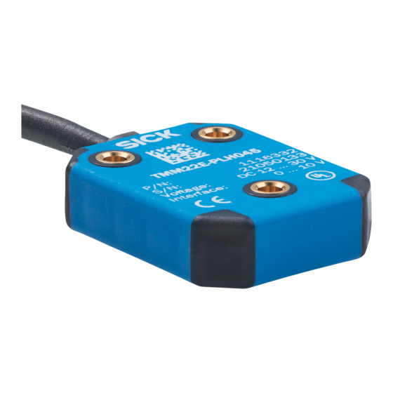
Table of Contents
Advertisement
Quick Links
Advertisement
Table of Contents

Summarization of Contents
About this document
Purpose of this document
Explains the document's objective for technical personnel regarding sensor integration and operation.
Explanation of symbols
Defines warning symbols (DANGER, WARNING, CAUTION, NOTICE) and informational notes for safety.
Safety Information
Intended Use
Specifies the designed applications for the inclination sensors, including solar and heavy-duty vehicles.
Improper Use
Warns against using sensors in explosion-hazardous areas or for non-intended purposes.
Personnel Qualification Requirements
Outlines the necessary training and qualifications for personnel handling the device.
Overview
Properties of the TMS/TMM22
Details technical features like MEMS technology, accuracy, analog interfaces, and enclosure ratings.
Areas of Application
Lists industries and applications such as photovoltaics, agricultural machinery, and wind power.
Technical Data
Technical Data for TMS/TMM22
Presents detailed specifications for TMS/TMM22, covering general, electrical, and mechanical parameters.
Measuring Axes
Illustrates the x and y axes for TMM22 and the z axis for TMS22 measuring principles.
Zero Point
Explains the factory-set zero points for TMM22 and TMS22 and the zero point reset procedure.
Transport and Storage
Transport
Provides guidelines for safe transportation, emphasizing proper packaging and handling.
Transport Inspection
Details procedures for checking deliveries for completeness and transit damage upon receipt.
Storage
Outlines recommended conditions for storing the device to maintain its integrity.
Mounting
Dimensional Drawing
Presents a technical drawing with dimensions and specifications for mounting the sensor.
Mounting Instructions
Details the fastening method using M3 screws and the recommended tightening torque.
Connection
PIN and Wire Allocation
Defines the pinout of the M12 connector and wire colors for TMS and TMM sensors.
Circuit Diagrams
Illustrates circuit diagrams for current and voltage outputs of the TMS/TMM22 sensors.
Length of Cable and Supply Voltage
Explains voltage drop in cables and calculates conductor resistance for current output configurations.
Load Resistance at Current Output
Provides a table and graph for permissible load resistances based on supply voltage for current outputs.
Description of Operation
Axis Assignment/Counting Direction
Explains the x/y axis assignment for TMM22 and the z-axis for TMS22, including counting directions.
Zero Point Adjustment
Details the factory zero points and the procedure for resetting the zero point using the TEACH function.
Signal Filtering
Describes the optional low-pass filter for suppressing vibration interference and its frequency response.
Status LED
Explains the meaning of the green and red LEDs for indicating operational status and faults.
Output Diagram
Shows example output signal paths (voltage/current) versus output angle for different sensor variants.
Resolution
Details the sensor resolution in relation to the measuring range, based on 16-bit sensor core and 14-bit DAC.
Annex
Conformities and Certificates
Provides information on obtaining declarations of conformity and certificates from the manufacturer's website.
Compliance with EU directives
States product conformity with relevant EU directives and applicable standards.
Compliance with UK statutory instruments
Declares product conformity with relevant UK statutory instruments and standards.


Need help?
Do you have a question about the TMM22 and is the answer not in the manual?
Questions and answers