Table of Contents
Advertisement
Quick Links
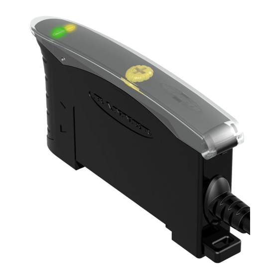
D10—Discrete Output
Datasheet
Low-cost, 10 to 30 V dc Sensor for use with Plastic Fiber Optics
WARNING: Not To Be Used for Personnel Protection
Never use this device as a sensing device for personnel protection. Doing so could lead to
serious injury or death. This device does not include the self-checking redundant circuitry necessary
to allow its use in personnel safety applications. A sensor failure or malfunction can cause either an
energized or de-energized sensor output condition.
Models
Red Beam
Green Beam
(660 nm)
(525 nm)
D10AFP
D10AFPG
D10AFPQ
D10AFPGQ
D10AFPY
D10AFPGY
D10AFPYQ
D10AFPGYQ
Features
12-Turn Sensitivity (Gain)
Control and Indicator
Turn Sensitivity control
clockwise to increase Gain
Delay Selector
LO/DO Select
Switch
1 To order the 9 m (30 ft) PVC cable model, add the suffix "W/30" to the cabled model number. For example, D10AFP W/30. Models with a quick disconnect
require a mating cordset.
Original Document
118431 Rev. B
•
Models available with visible red (660 nm) or visible green (525 nm) LED light
source
•
Sleek, ultra-slim 10 mm housing, mounts to standard 35 mm DIN rail
•
Solid-state, bipolar discrete outputs: one current sourcing (PNP) and one current
sinking (NPN)
•
High-speed models: 200-microsecond output response
•
Standard models: 500-microsecond output response plus crosstalk-avoidance
circuitry (for applications with multiple sensors)
•
Selectable Light/Dark Operate and 40 millisecond pulse stretcher (OFF-delay), via
two easy-to-operate slide switches
•
12-turn Sensitivity adjustment with relative position indicator
•
LED status indicators for Power ON and Light Sensed (AID
•
Models available with integral cable or Pico-style quick-disconnect
Response Time
500 microseconds
200 microseconds
Green
Power ON
LED
Yellow Signal
Strength LED
Switch
LED flashes
to indicate received
signal strength
14 November 2016
1
Cable
4-conductor 2 m (6.5 ft) Cable
4-pin Pico-style QD
4-conductor 2 m (6.5 ft) Cable
4-pin Pico-style QD
™
) indication
Output Type
Bipolar NPN/PNP Solid-state
118431
Advertisement
Table of Contents

Related Manuals for Banner D10AFPQ


Summarization of Contents
Installation
Fiber Optic Installation and Mounting
Guidance on installing fiber optics and physically mounting the sensor.
Wiring Diagram
Electrical connection diagrams for NPN and PNP output models.
Dimensions
Included Bracket Dimensions
Detailed measurements and hardware for the included mounting bracket.
Performance Curves
Opposed Mode Performance Curves
Graphs illustrating performance in opposed mode for various models.
Diffuse Mode Performance Curves
Graphs illustrating performance in diffuse mode for various models.
Configuration Instructions
Active Channel Select
Procedure for selecting the channel to teach and viewing configuration.
Static TEACH Procedure
Two-Point Static TEACH
Method for establishing a single switching threshold via two taught conditions.
Static TEACH and Manual Adjust
Using manual adjustment with static TEACH to fine-tune thresholds.
Contrast Values
Table relating signal difference to sensing reliability.
Dynamic TEACH Procedure
Dynamic TEACH and Adaptive Thresholds
Programming sensitivity during run conditions with adaptive threshold system.
Dynamic TEACH and Manual Adjust
Adjusting sensitivity using manual controls during dynamic TEACH.
Dynamic Contrast Values
Table relating signal difference to sensing reliability for dynamic TEACH.
Single-Point Window Set
Single-Point Window Set Method
Sets a sensing window with ON/OFF conditions outside the window.
Window Set and Manual Adjust
Using manual adjust to expand or contract the size of the sensing window.
Single-Point Light Set
Single-Point Light Set Method
Sets a threshold slightly below taught condition, affecting output state.
Light SET and Light/Dark Operate Selection
Teaches ON condition (Light Set) or OFF condition (Dark Set).
Single-Point Dark Set
Single-Point Dark Set Method
Sets threshold slightly above taught condition, affecting output state.
Dark Set and Light/Dark Operate Selection
Teaches OFF condition (Dark Set) or ON condition (Light Set).
Setup Mode Configuration Steps
Setup Mode Configuration Steps
Sequence of steps to configure sensor settings like operate mode and display.
Advanced Setup Procedures
Return to RUN Mode
Procedures for exiting setup modes and returning to normal operation.
Super-High-Speed Operation Note
Explanation of complementary outputs in Super-High-Speed mode.
Enter Advanced Setup Mode
Steps to access advanced configuration parameters.
Set Factory Default Settings
Procedure to restore sensor to its original factory default settings.
Dimensions
Included Bracket Dimensions
Detailed measurements and hardware for the included mounting bracket.
Sensor Setup Configuration Steps
Dynamic Event Stretcher (DES) Selection
Configure the DES to stretch output duration for accurate counting.
Display Mode Selection
Choose the display mode for health, signal level, or counter readouts.
Speed and Power Combination
Select sensor response speed and power level for optimal performance.
Advanced Setup Procedures
Enter Advanced Setup Mode
Steps to access advanced configuration parameters.
Set Factory Default Settings
Procedure to restore sensor to its original factory default settings.
Set Display Orientation
Configure the display orientation to normal or inverted.
Single-Point Window SET
Set Clear-State Light Level
Establishes the clear-state light level for single-point window setup.
Configuration Instructions
Analog Outputs Configuration
Configuring analog outputs using TEACH or Window SET methods.
Static TEACH Procedure
Two-Point Static TEACH
Method for establishing a single switching threshold via two taught conditions.
Static TEACH and Manual Adjust
Using manual adjustment with static TEACH to fine-tune thresholds.
Contrast Values
Table relating signal difference to sensing reliability.
Dynamic TEACH Procedure
Dynamic TEACH and Adaptive Thresholds
Programming sensitivity during run conditions with adaptive threshold system.
Dynamic TEACH and Manual Adjust
Adjusting sensitivity using manual controls during dynamic TEACH.
Dynamic Contrast Values
Table relating signal difference to sensing reliability for dynamic TEACH.
Single-Point Window Set
Single-Point Window Set Method
Sets a sensing window with ON/OFF conditions outside the window.
Window Set and Manual Adjust
Using manual adjust to expand or contract the size of the sensing window.
Single-Point Light Set
Single-Point Light Set Method
Sets a threshold slightly below taught condition, affecting output state.
Light SET and Light/Dark Operate Selection
Teaches ON condition (Light Set) or OFF condition (Dark Set).
Single-Point Dark Set
Single-Point Dark Set Method
Sets threshold slightly above taught condition, affecting output state.
Dark Set and Light/Dark Operate Selection
Teaches OFF condition (Dark Set) or ON condition (Light Set).
Setup Mode Operation
Access SETUP Mode
Procedure to enter the sensor's setup mode.
Select Light/Dark Operate
Configure sensor for light or dark operate conditions.
Select OFF-Delay Timing Enable
Configure the OFF-delay pulse stretcher for analog or discrete outputs.
Setup Mode Configuration
Select Display Parameters
Choose how the sensor display presents information.
Select Speed and Power Combination
Configure sensor response speed and power level for optimal performance.
Advanced Setup Configuration
Track Enable Settings
Configure tracking to set output 2 identical to output 1.
Factory Default Settings
Procedure to restore sensor to its original factory default settings.
Display Orientation Settings
Configure the display orientation to normal or inverted.
Dimensions
Included Bracket Dimensions
Detailed measurements and hardware for the included mounting bracket.
Static TEACH Procedure
Two-Point Static TEACH
Method for establishing a single switching threshold via two taught conditions.
Static TEACH and Manual Adjust
Using manual adjustment with static TEACH to fine-tune thresholds.
Relative Signal Difference
Table relating signal difference to sensing reliability.
Dynamic TEACH Procedure
Dynamic TEACH and Adaptive Thresholds
Programming sensitivity during run conditions with adaptive threshold system.
Dynamic TEACH and Manual Adjust
Adjusting sensitivity using manual controls during dynamic TEACH.
Relative Signal Difference
Table relating signal difference to sensing reliability for dynamic TEACH.
Single-Point Window Set
Single-Point Window Set Method
Sets a single ON condition extending above and below the taught condition.
Window Set and Manual Adjust
Using manual adjust to expand or contract the size of the sensing window.
Single-Point Light Set
Single-Point Light Set Method
Sets a threshold slightly below taught condition, affecting output state.
Light SET and Light/Dark Operate Selection
Teaches ON condition (Light Set) or OFF condition (Dark Set).
Single-Point Dark Set
Single-Point Dark Set Method
Sets threshold slightly above taught condition, affecting output state.
Dark Set and Light/Dark Operate Selection
Teaches OFF condition (Dark Set) or ON condition (Light Set).
Setup Mode Operation
Access Setup Mode
Procedure to enter the sensor's setup mode.
Select Setting Combination
Toggle through setting combinations using push buttons or remote line.
Return to Run Mode
Procedures for exiting setup modes and returning to normal operation.
Dimensions
Included Bracket Dimensions
Detailed measurements and hardware for the included mounting bracket.
Performance Curves
Red Beam Models Performance Curves
Graphs illustrating performance for red beam models in opposed and diffuse modes.
Green Beam Models Performance Curves
Graphs illustrating performance for green beam models in opposed and diffuse modes.
Accessories
Quick Disconnect Cordsets
Available cordset models, lengths, styles, dimensions, and pinouts.
DIN Rail Accessories
Accessories for mounting sensors on DIN rails, such as end stops and caps.
Need help?
Do you have a question about the D10AFPQ and is the answer not in the manual?
Questions and answers