Advertisement
Quick Links
Allure™ EC‑Smart‑Vue Sensor Series
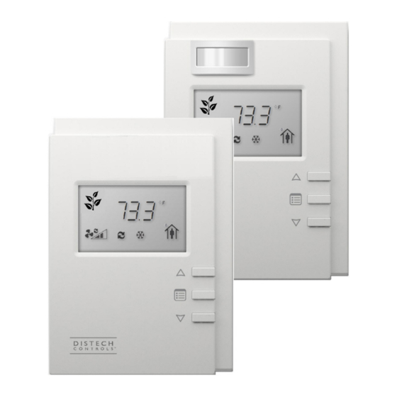
Figure 1:
(Left image) Allure EC Smart Vue, Allure EC Smart Vue-H/-C/-CH sensors. (Right image) Models equipped with a motion
sensing window in the upper left corner: Allure EC Smart Vue-M/-CM/-HM/-CHM sensors
Product Description
The Allure EC-Smart-Vue Series is designed to interface with Distech Controls' ECLYPSE™ series BACnet/IP and Wi-Fi Controllers, ECB series BAC-
®
net
Controllers and ECL series L
This line of communicating sensors with backlit display consists of eight models that provide precise environmental zone control. Models are available
with any combination of the following: temperature, humidity, CO
General Installation Requirements
For proper installation and subsequent operation of the device, pay special attention to the following recommendations:
£
Upon unpacking, inspect the contents of the carton for shipping damages. Do not install a damaged device.
£
Allow for proper clearance around the device's enclosure and wiring terminals to provide easy access for hardware configuration and maintenance.
£
Orient the device with the ventilation slots towards the top to permit proper heat dissipation.
£
Ensure proper ventilation of the device and avoid areas where corroding, deteriorating or explosive vapors, fumes or gases may be present.
Any type of modification to any Distech Controls product will void the product's warranty
Take reasonable precautions to prevent electrostatic discharge to the device when installing, servicing or during operation. Discharge
accumulated static electricity by touching one's hand to a well-grounded object before working with the device.
General Wiring Recommendations
Risk of Electric Shock: Turn off power before any kind of servicing to avoid electric shock.
£
All wiring must comply with electrical wiring diagrams as well as national and local electrical codes.
£
Comply with all network and power supply guidelines outlined in the Network Guide.
£
Use the screws, wall anchors, and wire nuts included for wall mounting and wiring.
®
W
Controllers.
ON
ORKS
2
, and motion sensor.
I n s t a l l a t i o n G u i d e
Advertisement

Related Manuals for Distech Controls Allure ECB-203


Summarization of Contents
General Installation Requirements
General Wiring Recommendations
Best practices and code compliance for all electrical wiring connections.
Mounting Instructions
Wall Mounting Installation Procedure
Step-by-step instructions for mounting the device on dry walls.
Connector and Jumper Configuration
CO₂ Sensor Calibration and Accuracy
Information on CO₂ sensor factory calibration and operational accuracy.
Subnetwork Bus Topology and EOL Terminations
EOL Terminations for Non-ECB/ECL-600 Controllers
EOL termination settings for specific controller series without Smart Room Control.
EOL Terminations for ECB/ECL-600 Controllers
EOL termination settings for ECB/ECL-600 series and Smart Room Control scenarios.
Troubleshooting Common Issues
Sensor Screen and Communication Errors
Diagnosing issues with the display, connectivity, and general communication problems.
CO₂ Sensor Reading Inconsistencies
Addressing issues with CO₂ sensor accuracy, NULL output, or inconsistent readings.
Error Code Interpretation Guide
Understanding and resolving error codes displayed by the sensor.
Need help?
Do you have a question about the Allure ECB-203 and is the answer not in the manual?
Questions and answers