
Related Manuals for Sullivan-Palatek 40D


Summary of Contents for Sullivan-Palatek 40D
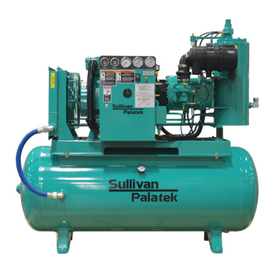
- Page 1 USER MANUAL INDUSTRIAL ELECTRIC COMPRESSOR \ 15–40 HP \ D-SERIES 15D, H15D, 20D, H20D, HH20D 25D, HH25D, 25D4, H25D4 30D7, H30D7, HH30D7 40D, H40D, HH40D ELECTRO-MECHANICAL CONTROLS Document: 18730-049 / 00 Issued: June 30, 2017...
- Page 2 DOCUMENT INFORMATION © Sullivan-Palatek, Inc. ALL RIGHTS RESERVED Part Number: 18730-049 Revision: 00 CONTACT INFORMATION Sullivan-Palatek, Inc. 1201 West US Highway 20 Michigan City, Indiana 46360 Phone: (219) 874-2497 Fax: (219) 872-5043 Toll Free: (800) 438-6203 Website: www.sullivan-palatek.com RECORD KEEPING Record the model and serial number of the compressor for future reference when contacting the Factory for service or parts.
- Page 3 18 months from shipment from Sullivan-Palatek to initiate the warranty. If the warranty registration is not initiated in this manner the warranty effective date will be deemed to be the date of shipment from Sullivan-Palatek. Service under this warranty is obtained by contacting the authorized Sullivan-Palatek distributor before the expiration of the warranty.
- Page 4 Sullivan-Palatek’s Obligations: Sullivan-Palatek, Inc. will repair or replace, at Sullivan-Palatek’s option, any defective part. Sullivan-Palatek will pay the reasonable labor cost of making the repair or installing the replacement part when coverage includes labor, and will pay ground freight for the return of defective parts and shipment of replacement parts.
-
Page 5: About This Manual
MANUAL ORGANIZATION Anyone operating or servicing the Sullivan-Palatek air compressor should read this entire manual and be familiar with its information. The following is a quick guide to the contents in this manual: SECTION 1: INTRODUCTION This section contains important basic information regarding the compressor, such as safety precautions and warranty information. - Page 6 AbOUT THIS MANUAL...
-
Page 7: Table Of Contents
CONTENTS AbOUT THIS MANUAL..........V Safety Instructions. - Page 8 MAINTENANCE ........... . .45 Maintenance Schedule .
-
Page 9: Introduction
INTRODUCTION TOPICS IN THIS SECTION: » General Compressor Safety Precautions ............2 »... -
Page 10: General Compressor Safety Precautions
SAFETY DECALS Sullivan-Palatek compressors are all equipped with brightly colored, weather-resistant, pictorial/verbal decals. These are designed to warn the operator against potential hazards in order to minimize risk of property damage, bodily injury and/or death. -
Page 11: Screw Compressor Air End Exchange Program
All bearings and seals in the factory-remanufactured air end are replaced. All other parts not meeting Sullivan-Palatek’s quality standards are also replaced. A remanufactured air end has a warranty period of 12 months from start-up date or 18 months from date of shipment. - Page 12 INTRODUCTION...
-
Page 13: Specifications
15D, H15D ........ -
Page 14: Technical Data
TECHNICAL DATA 2.1.1 15D, H15D COMPRESSOR DATA H15D Capacity acfm Pressure @ Full Load psig (bar) 125 (8.6) 150 (10.3) Minimum Pressure psig (bar) 60 (4.1) 70 (4.8) Motor Output (60 Hz) hp (kW) 15 (11.2) 15 (11.2) Motor Speed... -
Page 15: 20D, H20D, Hh20D
2.1.2 20D, H20D, HH20D COMPRESSOR DATA H20D HH20D Capacity acfm Pressure @ Full Load psig (bar) 125 (8.6) 150 (10.3) 175 (12.1) Minimum Pressure psig (bar) 60 (4.1) 70 (4.8) 70 (4.8) Motor Output (60 Hz) hp (kW) 20 (14.9) 20 (14.9) 20 (14.9) Motor Speed... - Page 16 2.1.3 COMPRESSOR DATA Capacity acfm Pressure @ Full Load psig (bar) 125 (8.6) Minimum Pressure psig (bar) 60 (4.1) Motor Output (60 Hz) hp (kW) 25 (18.6) Motor Speed 3,550 Motor Output @ Full Load hp (kW) 27 (20.1) Motor Output @ 100 psig hp (kW) 24 (17.9) Driven Rotor Coupling...
-
Page 17: 25D4, H25D4, Hh25D4
2.1.4 25D4, H25D4, HH25D4 COMPRESSOR DATA 25D4 H25D4 HH25D4 Capacity acfm Pressure @ Full Load psig (bar) 125 (8.6) 150 (10.3) 175 (12.1) Minimum Pressure psig (bar) 60 (4.1) 70 (4.8) 70 (4.8) Motor Output (60 Hz) hp (kW) 25 (18.6) 25 (18.6) 25 (18.6) Motor Speed... -
Page 18: 30D7, H30D7, Hh30D7
2.1.5 30D7, H30D7, HH30D7 COMPRESSOR DATA 30D7 H30D7 HH30D7 Capacity acfm Pressure @ Full Load psig (bar) 125 (8.6) 150 (10.3) 175 (12.1) Minimum Pressure psig (bar) 60 (4.1) 70 (4.8) 70 (4.8) Motor Output (60 Hz) hp (kW) 30 (22.4) 30 (22.4) 30 (22.4) Motor Speed... -
Page 19: 40D, H40D, Hh40D
2.1.6 40D, H40D, HH40D COMPRESSOR DATA H40D HH40D Capacity acfm Pressure @ Full Load psig (bar) 125 (8.6) 150 (10.3) 175 (12.1) Minimum Pressure psig (bar) 60 (4.1) 70 (4.8) 70 (4.8) Motor Output (60 Hz) hp (kW) 40 (29.8) 40 (29.8) 40 (29.8) Motor Speed... -
Page 20: Dimensions-Open, Base Mount, Air-Cooled
DIMENSIONS–OPEN, BASE MOUNT, AIR-COOLED FIGURE 2-1. GA-15-40D-AC-BM-OPEN SPECIFICATIONS... -
Page 21: Dimensions-Enclosed, Base Mount, Air-Cooled
DIMENSIONS–ENCLOSED, BASE MOUNT, AIR-COOLED FIGURE 2-2. GA-15-40D-AC-BM-VERT-ENCL SPECIFICATIONS... -
Page 22: Dimensions-Open, Base Mount, Water-Cooled
DIMENSIONS–OPEN, BASE MOUNT, WATER-COOLED FIGURE 2-3. GA-15D-30D-WC-BM-HORZ-OPEN-GAUGES SPECIFICATIONS... -
Page 23: Dimensions-Enclosed, Base-Mount, Water-Cooled
DIMENSIONS–ENCLOSED, BASE-MOUNT, WATER-COOLED FIGURE 2-4. GA-15-40D-WC-BM-ENCL-GAUGES SPECIFICATIONS... -
Page 24: Dimensions-Open, Platform Mount, Air-Cooled
DIMENSIONS–OPEN, PLATFORM MOUNT, AIR-COOLED FIGURE 2-5. GA-15-40D-AC-PLAT-OPEN-GAUGES SPECIFICATIONS... -
Page 25: Dimensions-Enclosed, Platform Mount, Air-Cooled
DIMENSIONS–ENCLOSED, PLATFORM MOUNT, AIR-COOLED FIGURE 2-6. GA-15-40D-AC-PM-VERT-ENCL SPECIFICATIONS... -
Page 26: Dimensions-Open, Platform Mount, Water-Cooled
DIMENSIONS–OPEN, PLATFORM MOUNT, WATER-COOLED FIGURE 2-7. GA-15D-30D-WC-PLAT-HORZ-OPEN-GAUGES SPECIFICATIONS... -
Page 27: Dimensions-Horizontal Receiver (120 Gallon)
DIMENSIONS–HORIZONTAL RECEIVER (120 GALLON) FIGURE 2-8. AS812-120 R00 SPECIFICATIONS... -
Page 28: Dimensions-Horizontal Receiver (200 Gallon)
2.10 DIMENSIONS–HORIZONTAL RECEIVER (200 GALLON) FIGURE 2-9. AS812-200 R00 SPECIFICATIONS... -
Page 29: Dimensions-Horizontal Receiver (240 Gallon)
2.11 DIMENSIONS–HORIZONTAL RECEIVER (240 GALLON) FIGURE 2-10. AS812-240 R00 SPECIFICATIONS... -
Page 30: Piping And Instrumentation (Air-Cooled)
2.12 PIPING AND INSTRUMENTATION (AIR-COOLED) FIGURE 2-11. GA-P&I-S R02 SPECIFICATIONS... -
Page 31: Piping And Instrumentation (Water-Cooled)
2.13 PIPING AND INSTRUMENTATION (WATER-COOLED) FIGURE 2-12. P&I-15-40-WC-GAUGES R00 SPECIFICATIONS... -
Page 32: Wiring Diagram, Mfv (208/230/460V)
2.14 WIRING DIAGRAM, MFV (208/230/460V) TOLERANCES PALATEK SULLIVAN UNLESS OTHERWISE NOTED DIMENSIONS ARE IN INCHES 1201 Highway 20 West Michigan City, Indiana 46360 ANGLES..±1/2 ° TITLE: MACHINED..±1/64" 15-40HP EM, MFV WITH ESTOP STRUCTURAL..±1/16" 0" TO 12"..030" 12" TO 36"..060" SIZE DRAWN BY: DWG NO. -
Page 33: Wiring Diagram, Mfv (575V)
2.15 WIRING DIAGRAM, MFV (575V) TOLERANCES PALATEK SULLIVAN UNLESS OTHERWISE NOTED DIMENSIONS ARE IN INCHES 1201 Highway 20 West Michigan City, Indiana 46360 ANGLES..±1/2 ° TITLE: MACHINED..±1/64" 575V, 15-40HP EM, MFV WITH ESTOP STRUCTURAL..±1/16" 0" TO 12"..030" 12" TO 36"..060" SIZE DRAWN BY: DWG NO. - Page 34 SPECIFICATIONS...
-
Page 35: Component Description
COMPONENT DESCRIPTION TOPICS IN THIS SECTION: » Air Compressor Package ..............28 »... -
Page 36: Air Compressor Package
AIR COMPRESSOR PACKAGE The air compressor package consists of a rotary screw compressor unit, air-cooled lubrication and cooling system, discharge system, intake and capacity control system, and monitoring system. COMPRESSION CYCLE During operation, two helically-grooved rotors mesh to compress air. Intake air is compressed as the male lobes roll down the female grooves, pushing trapped air along, compressing it until a female groove uncovers the discharge port in the end of the stator and delivers smooth-flowing, pulse-free air to the receiver. -
Page 37: Air/Oil Discharge System
3.4.2 PRESSURE RELIEF VALVE The pressure relief valve will open to relieve excess pressure in the sump tank if the pressure exceeds the set point. The valve will automatically reset to its reset pressure point after the excess pressure is relieved. The pressure relief valve is ASME compliant and rated at 200 psig to match the rating of the tank. -
Page 38: Cooling And Lubricating System
It is a sealant, sealing the rotors to reduce leakage paths between the rotors and between the stator housing. Rotary screw compressor units require specialized lubricant to maintain proper performance. Use of Sullivan-Palatek lubricants is recommended. Refer to 8.4 Compressor Lubricants on page 62. 3.6.2 TEMPERATURE CONTROL VALVE (THERMOSTATIC VALVE) The temperature control valve (also referred to as a thermostatic valve) regulates the flow of oil to the oil cooler based on temperature. -
Page 39: Air Inlet And Capacity Control System
FIRST USED ON: SCALE: SHEET THIS DRAWING AND ALL INFORMATION THEREIN IS THE PROPERTY OF SULLIVAN-PALATEK, INC. IS CONFIDENTIAL AND MUST NOT BE MADE PUBLIC OR COPIED. # COMPONENT # COMPONENT IT IS LOANED SUBJECT TO RETURN UPON DEMAND, IS NOT TO BE USED DIRECTLY OR INDIRECTLY IN ANYWAY DETRIMENTAL TO SULLIVAN-PALATEK'S INTEREST. - Page 40 START-UP LEGEND Line Pressure Dry Side SULLIVAN-PALATEK 12/10/13 Regulated Air 1201 West US Highway 20, Michigan City IN 46360 1-800-438-6203 108-127MM 15-60HP FIGURE 3-3. 15–60HP CONTROL SYSTEM (START-UP) NOTE! Image may not represent your exact model. When the compressor is started, a 20-second timer is energized to ensure the compressor is up to proper speed and minimum design pressure has been achieved.
- Page 41 FULL-LOAD LEGEND Line Pressure Dry Side SULLIVAN-PALATEK 12/10/13 Regulated Air 1201 West US Highway 20, Michigan City IN 46360 1-800-438-6203 108-127MM 15-60HP FIGURE 3-4. 15–60HP CONTROL SYSTEM (FULL LOAD) NOTE! Image may not represent your exact model. After the initial start-up, the timer will force the electrical components controlling the low pressure control to drop out.
- Page 42 MODULATION LEGEND Line Pressure Dry Side SULLIVAN-PALATEK 12/10/13 Regulated Air 1201 West US Highway 20, Michigan City IN 46360 1-800-438-6203 108-127MM 15-60HP FIGURE 3-5. 15–60HP CONTROL SYSTEM (MODULATION) NOTE! Image may not represent your exact model. Modulation will occur between the regulated set point and the setting of the pressure switch, which should be 10 psi (0.7 bar) over regulated set pressure to create a 10 psi (0.7 bar) modulating range.
- Page 43 UNLOAD LEGEND Line Pressure Dry Side SULLIVAN-PALATEK 12/10/13 Regulated Air 1201 West US Highway 20, Michigan City IN 46360 1-800-438-6203 108-127MM 15-60HP FIGURE 3-6. 15–60HP CONTROL SYSTEM (UNLOAD) NOTE! Image may not represent your exact model. Unload status occurs when the customer’s demand pressure set point is achieved with an additional 10 psi (0.7 bar) overshoot.
-
Page 44: Monitoring System
3.7.2 INLET CONTROL VALVE The inlet control valve is the main control for air capacity within the air compressor. It is equipped with a poppet disc for inlet control as well as reverse flow check. The valve is initially opened at start-up by suction created by rotating screws in the compressor unit. -
Page 45: Installation
INSTALLATION TOPICS IN THIS SECTION: » Receiving ................. .38 »... -
Page 46: Receiving
RECEIVING Every Sullivan-Palatek air compressor has been operated and tested at the Factory prior to shipment. The testing ensures that the air compressor is functioning properly and will deliver its rated pressure and capacity. Regardless of the care taken at the Factory, there is a possibility that the air compressor could be damaged during shipment. -
Page 47: Electrical Connections
The recommended water pressure range is 40–75 psig (2.8–5.2 bar). Refer to Technical Data on page 6 for cooling water flow rates. Water flow rates will vary by operating conditions. Consult the nearest Sullivan-Palatek representative for flow rates based on criteria other than what is listed. -
Page 48: Compressed Air System
COMPRESSED AIR SYSTEM Connect to plant air system with a flexible connector with a minimum rating of 200 psi (13.8 bar) and 245°F (118°C). Piping should be large enough in diameter to minimize pressure drop. Support piping so that stress is not transmitted to the compressor. -
Page 49: Operation
OPERATION TOPICS IN THIS SECTION: » Electro-Mechanical Controls ..............42 »... -
Page 50: Electro-Mechanical Controls
ELECTRO-MECHANICAL CONTROLS FIGURE 5-1. E/M CONTROLS OPEN COMPRESSOR FIGURE 5-2. E/M CONTROLS ENCLOSED COMPRESSOR OPERATION... -
Page 51: Modes Of Operation
TABLE 5-1. E/M CONTROLS COMPONENTS ITEM COMPONENT DESCRIPTION Oil Filter Differential Displays pressure drop across the oil filter(s) for determining when to maintenance Separator Differential Displays pressure drop across the separator element for determining when to maintenance Temperature Displays temperature of air end oil leaving the air end for monitoring Line Pressure Displays the line pressure (air leaving the minimum pressure valve) for monitoring... -
Page 52: Normal Stop
NORMAL STOP Close the service valve. Allow sump pressure to fall to 30-45 psig. Turn the selector switch to the OFF position. RESTARTS If the compressor shuts down unexpectedly, special procedures must be followed to safely restart the compressor. Below are the procedures for safely restarting the compressor, depending on the reason for the shutdown. -
Page 53: Maintenance
MAINTENANCE TOPICS IN THIS SECTION: » Maintenance Schedule ...............46 »... -
Page 54: Maintenance Schedule
Sullivan-Palatek recommends oil sampling as the best guide for your fluid change interval. Changing fluid once a year may not be adequate or it can be excessive. For this reason an hourly service on lubricants is merely a guide. Please consult your factory-trained servicing distributor for questions concerning your lubricant life and Sullivan-Palatek’s lubricant sampling... -
Page 55: General Maintenance Safety
GENERAL MAINTENANCE SAFETY WARNING! Never assume a compressor is safe to work on just because it is not operating. It could restart at any time. WARNING! Do not allow oil to accumulate on, in or around acoustic noise material. Immediately replace any oil- soaked material after cleaning enclosure surface with nonflammable solvent. -
Page 56: Compressor Lubricant
COMPRESSOR LUbRICANT Refer to Chapter 8.4 Compressor Lubricants on page 62 for additional information about lubricants offered by Sullivan-Palatek. CAUTION! Never mix synthetic lubricants with hydrocarbon lubricants. Never mix synthetic lubricants manufactured from different base products. Severe damage to the compressor system may result. -
Page 57: Oil Sample For Analysis
Remove any remaining oil by turning the compressor unit by hand. Remove oil filter element. FLUSH COMPRESSOR Pour as much flush lubricant into the inlet as was removed from the compressor. Add flush lubricant to the sump tank to maximum fill level. Install a new oil filter element and jog compressor. - Page 58 SAMPLE OIL FROM SUMP TANK Run the compressor long enough to reach normal operating temperatures. Follow 6.3 Stopping for Maintenance procedures. Remove the drain plug from the end of the drain line at the bottom of the sump tank. Open the drain valve and drain any water from the sump tank. Discard in an approved manner.
-
Page 59: Oil Filter
tooltip OIL FILTER The oil filter should be replaced after the first 50 hours of operation and then every 1,000 hours (or quarterly) or if the filter differential pressure gauge exceeds 15 psid. The oil filter element is mounted to the side of the compressor unit. -
Page 60: Air/Oil Separator
AIR/OIL SEPARATOR The separator element should be replaced every 4,000 hours (or once a year). Refer to Figure 6-5. Sump The separator element is located in the top side of Tank the sump tank under the tank lid. To replace the element, access panels have been supplied in the roof. -
Page 61: Air Filter
tooltip AIR FILTER The air filter should be replaced every 1,000 hours or more often in severe or outside conditions. The inlet filter is a critical filter, protecting the compressor from exterior foreign materials. Keeping the inlet filter element clean will help maintain proper capacity rating of the compressor. Filter Body Secondary Filter Element Primary Filter Element... -
Page 62: Pressure Adjustment
6.12 PRESSURE ADJUSTMENT The intervals at which the compressor loads, modulates and unloads are controlled by adjustable settings. The load and unload settings are adjusted on the control pressure switch (CPS). The modulating pressure is adjusted on the control pressure regulating valve. These settings are preset at the factory based on the original order. -
Page 63: Troubleshooting
TROUbLESHOOTING TOPICS IN THIS SECTION: » Introduction................56 »... -
Page 64: Introduction
INTRODUCTION This section contains instructions for troubleshooting the equipment following a malfunction. Each symptom of trouble for a component or system is followed by a list of probable causes of the trouble and suggested procedures to be followed to eliminate the cause. The procedures listed should be performed in the order in which they are listed, although the order may be varied if the need is indicated by conditions under which the trouble occurred. -
Page 65: Line Pressure Rises Above Unload Pressure
LINE PRESSURE RISES AbOVE UNLOAD PRESSURE POSSIbLE CAUSE REMEDY Leak in control system tubing causing loss of Replace tubing. pressure signals Defective solenoid valve Repair or replace solenoid valve. Faulty inlet valve Repair or replace inlet valve. EXCESSIVE LUbRICANT CONSUMPTION POSSIbLE CAUSE REMEDY Clogged separator oil return line... - Page 66 TROUBLESHOOTING...
-
Page 67: Parts Catalog
PARTS CATALOG TOPICS IN THIS SECTION: » Ordering Parts................60 »... -
Page 68: Ordering Parts
Use the space provided on the inside cover of the manual to record the model and serial number of the compressor for future reference. 8.1.1 CONTACT INFORMATION For replacement parts and manuals contact: Sullivan-Palatek, Inc. 1201 West US Highway 20 Michigan City, Indiana 46360 Phone: (219) 874-2497... -
Page 69: Recommended Spare Parts List
KIT, OIL ANALYSIS 00061-005 LUBRICANT, PALASYN 45 (5 GALLON) NOTE! Use only service parts supplied or recommended by Sullivan-Palatek. Use of substitutes may void warranty. See WARRANTY for details. 8.3.1 MAINTENANCE KITS Maintenance kits are available. Contact Distributor for more information. -
Page 70: Compressor Lubricants
For this reason an hourly service on lubricants is merely a guide. Please consult your factory-trained servicing distributor for questions concerning your lubricant life and Sullivan-Palatek’s lubricant sampling program. See 6.6 Oil Sample for Analysis on page 43 for additional information. - Page 71 FLUID LIFE Fluid life is maximum hours based on temperature only. Oil change interval to be based on oil per analysis findings. » 8,600 hours (or 1 year) ORDERING OPTIONS DESCRIPTION PART NUMbER LUBRICANT, PAL-EXTRA 44, 5 GALLON PAIL 00066-005 LUBRICANT, PAL-EXTRA 44, 55 GALLON DRUM 00066-055 8.4.4...
- Page 72 8.4.6 PAL-32 LL (FOOD GRADE) PAL-32 LL is a full synthetic compressor lubricant formulated from the highest quality polyalphaolefin (PAO) base oils with a superior proprietary additive package to achieve long life. This long-life compressor lubricant provides significantly improved wear protection, oxidation stability and lubricity over the currently available H-1 food grade synthetic oils allowing the service life to increase by 50% to 100%.
- Page 73 For this reason an hourly service on lubricants is merely a guide. Please consult your factory-trained servicing distributor for questions concerning your lubricant life and Sullivan-Palatek’s lubricant sampling program. See 6.6 Oil Sample For Analysis on page 49 for additional information.
-
Page 74: Compressor, Frame And Drive Assembly (15Hp)
COMPRESSOR, FRAME AND DRIVE ASSEMBLY (15HP) FIGURE 8-1. AS801-015DT-TE R00 PARTS CATALOG... - Page 75 PARTS CATALOG...
-
Page 76: Compressor, Frame And Drive Assembly (20-30Hp)
COMPRESSOR, FRAME AND DRIVE ASSEMBLY (20–30HP) FIGURE 8-2. AS801-030D7H-TE REV 00 PARTS CATALOG... - Page 77 PARTS CATALOG...
-
Page 78: Compressor, Frame And Drive Assembly (40Hp)
COMPRESSOR, FRAME AND DRIVE ASSEMBLY (40HP) FIGURE 8-3. AS801-040DS-TE R00 PARTS CATALOG... - Page 79 PARTS CATALOG...
-
Page 80: Pneumatic Controls Assembly (15-40Hp)
PNEUMATIC CONTROLS ASSEMBLY (15–40HP) FIGURE 8-4. AS802-01540D R00 PARTS CATALOG... - Page 81 PARTS CATALOG...
-
Page 82: Control Panel Assembly (15-40Hp)
CONTROL PANEL ASSEMBLY (15–40HP) FIGURE 8-5. AS809-030DG R00 PARTS CATALOG... - Page 83 PARTS CATALOG...
-
Page 84: Air Inlet Assembly (15-30Hp)
8.10 AIR INLET ASSEMBLY (15–30HP) FIGURE 8-6. AS805-030D7H-TE R00 PARTS CATALOG... - Page 85 PARTS CATALOG...
-
Page 86: Air Inlet Controls (15-30Hp)
8.11 AIR INLET CONTROLS (15–30HP) FIGURE 8-7. AS820-005 R03 PARTS CATALOG... - Page 87 PARTS CATALOG...
-
Page 88: Air Inlet Assembly (40Hp)
8.12 AIR INLET ASSEMBLY (40HP) FIGURE 8-8. AS805-040DS-TE REV 00 PARTS CATALOG... - Page 89 PARTS CATALOG...
-
Page 90: Air Inlet Controls (40Hp)
8.13 AIR INLET CONTROLS (40HP) FIGURE 8-9. AS820-003 R03 PARTS CATALOG... - Page 91 PARTS CATALOG...
-
Page 92: Discharge Assembly (15Hp)
8.14 DISCHARGE ASSEMBLY (15HP) FIGURE 8-10. AS803-015DT-TE REV 00 PARTS CATALOG... - Page 93 PARTS CATALOG...
-
Page 94: Discharge Assembly (20-30Hp)
8.15 DISCHARGE ASSEMBLY (20–30HP) FIGURE 8-11. AS803-030D7H-TE R00 PARTS CATALOG... - Page 95 PARTS CATALOG...
-
Page 96: Discharge Assembly (40Hp)
8.16 DISCHARGE ASSEMBLY (40HP) FIGURE 8-12. AS803-040DS-TE R00 PARTS CATALOG... - Page 97 PARTS CATALOG...
-
Page 98: Cooling & Lubrication Assembly, Air-Cooled (15-25Hp)
8.17 COOLING & LUBRICATION ASSEMBLY, AIR-COOLED (15–25HP) FIGURE 8-13. AS804-015DT-TE R00 PARTS CATALOG... - Page 99 PARTS CATALOG...
-
Page 100: Cooling & Lubrication Assembly, Air-Cooled (30Hp)
8.18 COOLING & LUBRICATION ASSEMBLY, AIR-COOLED (30HP) FIGURE 8-14. AS804-030D7H-TE 30HP R00 PARTS CATALOG... - Page 101 PARTS CATALOG...
-
Page 102: Cooling & Lubrication Assembly, Air-Cooled (40Hp)
8.19 COOLING & LUBRICATION ASSEMBLY, AIR-COOLED (40HP) FIGURE 8-15. AS804-040DS-TE R00 PARTS CATALOG... - Page 103 PARTS CATALOG...
-
Page 104: Cooling & Lubrication Assembly, Water-Cooled (15-40Hp)
8.20 COOLING & LUBRICATION ASSEMBLY, WATER-COOLED (15–40HP) FIGURE 8-16. AS804-040D-WC R01 PARTS CATALOG... - Page 105 PARTS CATALOG...
-
Page 106: Enclosure Assembly, Horizontal Flow, Air-Cooled (15-40Hp)
8.21 ENCLOSURE ASSEMBLY, HORIZONTAL FLOW, AIR-COOLED (15–40HP) FIGURE 8-17. AS77149-1540HOR R00 PARTS CATALOG... - Page 107 PARTS CATALOG...
-
Page 108: Enclosure Assembly, Updraft, Air-Cooled (15-30Hp)
8.22 ENCLOSURE ASSEMBLY, UPDRAFT, AIR-COOLED (15–30HP) FIGURE 8-18. AS77149-1540 R00 PARTS CATALOG... - Page 109 PARTS CATALOG...
-
Page 110: Enclosure Assembly, Water-Cooled (15-40Hp)
8.23 ENCLOSURE ASSEMBLY, WATER-COOLED (15–40HP) FIGURE 8-19. AS77149-1550W R00 PARTS CATALOG... - Page 111 PARTS CATALOG...
- Page 112 NOTES...
- Page 113 NOTES...
- Page 114 1201 West US Highway 20 Michigan City, Indiana 46360 Phone: 219.874.2497 Fax: 219.809.0203 info@palatek.com www.sullivan-palatek.com...
Need help?
Do you have a question about the 40D and is the answer not in the manual?
Questions and answers