
Related Manuals for Sullivan-Palatek D185PIZP


Summary of Contents for Sullivan-Palatek D185PIZP
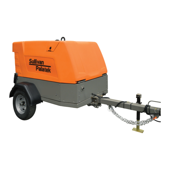
- Page 1 OPERATION & SERVICE MANUAL WHEEL-MOUNTED PORTABLE COMPRESSOR \ 185 CFM D185PIZP ISUZU ENGINE TIER 4 FINAL 05018730-0315 / 00 Issued: August, 2023...
- Page 2 DOCUMENT INFORMATION © Sullivan-Palatek, Inc. ALL RIGHTS RESERVED Part Number: 05018730-0315 Revision: 00 CONTACT INFORMATION Sullivan-Palatek, Inc. 1201 West US Highway 20 Michigan City, Indiana 46360 Phone: (219) 874-2497 Fax: (219) 872-5043 Toll Free: (800) 438-6203 Website: www.sullivan-palatek.com RECORD KEEPING...
-
Page 3: Table Of Contents
Normal Stopping..............11 Sullivan-Palatek Electronic Controller (SPEC) Operational Instructions ....11 Operating Under Extreme Conditions . - Page 4 MAINTENANCE ............25 Maintenance Schedule .
-
Page 5: Warranty
Sullivan-Palatek or 36 months from delivery to the first user. Two stage high pressure compressor models: the first to expire; 30 months from shipment by Sullivan-Palatek or 24 months from delivery to the first user. Remainder of new portable air compressor machines: the first to expire; 18 months from shipment by Sullivan-Palatek or 12 months from delivery to the first user. - Page 6 WARRANTY...
-
Page 7: About This Manual
II.2 MANUAL ORGANIZATION Anyone operating or servicing the Sullivan-Palatek air compressor should read this entire manual and be familiar with its information. The following is a quick guide to the contents in this manual: SECTION 1: SAFETY This section contains important basic information regarding general safety precautions for maintaining and operating air compressors. - Page 8 ABOUT THIS MANUAL...
-
Page 9: Safety
SAFETY TOPICS IN THIS SECTION: » General Safety ................2 »... -
Page 10: General Safety
GENERAL SAFETY Safety is a prime consideration in the design and manufacture of the compressor components. Ultimately, the responsibility for safe operation rests with the individuals who use and maintain the compressor. The following safety precautions are offered as a guide for the safe operation and maintenance of this machinery: »... -
Page 11: Moving Parts
» Anti-freeze compound used in air line anti-icing systems contains methanol, which is flammable. Use systems and refill with compound only in well-ventilated areas, away from heat, open flames, or sparks. Do not expose any part of these systems or the anti-freeze compound to temperatures above 150°F (65°C). Vapors from the anti-freeze compound are heavier than air. Do not store compound or discharge treated air in confined or unventilated area. Do not store containers or anti-freeze compound in direct sunlight. » Store flammable liquids in suitable containers and cabinets, away from sources of sparks and heat. 1.3.2 BATTERIES AND WIRING WARNING! Fire or explosion can result from electrical arcing from terminal, battery connections and improperly... -
Page 12: Toxic And Irritating Substances
Under specific guidelines and in full compliance with OSHA Standards 29 CFR 1920 and any other federal, state, or local codes or regulations compressed air can be used for breathing air. Sullivan-Palatek does not provide equipment and instructions for this application and its products are not produced for this application or use. -
Page 13: Transporting And Locating
TRANSPORTING AND LOCATING TOPICS IN THIS SECTION: » Receiving ................. . . 6 »... -
Page 14: Receiving
RECEIVING Each compressor is operated and tested at the factory before shipment. This testing assures that the unit is operating properly and that the compressor will deliver its rated capacity. Regardless of the care taken at the factory, there is a possibility that adjustments may be altered or damage may occur during shipment. For this reason it is recommended that the unit be checked for proper operation and carefully inspected before it is put in service. The machine should be observed for any possible malfunction during the first few hours of operation. -
Page 15: Preparing To Tow
PREPARING TO TOW » Properly drain and dispose of any fluids in the containment frame before towing. » Before beginning to tow the compressor, test brake operation, including breakaway switch operation if provided or if equipped. » Damaged or worn towing components can result in separation of the compressor from the towing vehicle during towing. -
Page 16: Parking Or Locating Compressor
» Observe and follow all local, state, and federal traffic laws. Note and adhere to speed limits and minimum highway speed. » Do not exceed maximum towing speeds. Reduce speed accordingly, as dictated by posted signs, weather, road, or terrain conditions. » Remember that portable air compressors may approach or exceed the weight of the towing vehicle. Maintain increased stopping distance accordingly. -
Page 17: Operation
Normal Stopping ................11 » Sullivan-Palatek Electronic Controller (SPEC) Operational Instructions ......11 »... -
Page 18: General Operating Safety
GENERAL OPERATING SAFETY » Allow at least ten feet of unobstructed area in front of cooling air inlets and outlets to assure good airflow. » If compressor is connected to a common header with one or more compressors, a check valve must be provided between each compressor and header. -
Page 19: Normal Stopping
Run engine at low idle for 2 minutes. Open and close the service valve to reduce pressure to approximately 75 psi or less. Press ignition switch to OFF. SULLIVAN-PALATEK ELECTRONIC CONTROLLER (SPEC) OPERATIONAL INSTRUCTIONS The buttons for operation will be referred to numerically based upon the image at right. - Page 20 USER SETTINGS SCREEN Brightness, contrast, language, units, and time and date can be accessed in this screen. Buttons 1 and 2 cycle between the selections; Button 3 returns back to the Menu screen; Buttons 4 and 5 adjust the setting of the selected item.
-
Page 21: Operating Under Extreme Conditions
DIAGNOSTIC MESSAGE SCREEN This screen will pop up when the machine encounters a Fault/SPN/FMI code. The specific fault will be displayed, as well as an indication if a shutdown will occur. If a diagnostic fault is hidden, a warning icon will be displayed on the Gauge screen. -
Page 22: Jump-Starting Battery
» Install an appropriate flow-limiting valve between the compressor service air outlet and the shut-off (throttle) valve when an air hose exceeding 0.5-inch inside diameter is to be connected to the shut-off (throttle) valve. This is to reduce pressure in case of hose or connection failure, per OSHA Standard 29 CFR 1926.302 (as) (7). » When a hose will be used to supply a manifold, install an appropriate flow-limiting valve between the manifold and each air hose exceeding 0.5-inch inside diameter that is to be connected to the manifold. This will reduce pressure in case of hose failure. - Page 23 Connect the other end of the BLACK (negative) cable to an unpainted metal surface on the compressor engine with the dead battery. Make sure all the jumper cable clips have a good connection (good clamping force) before attempting to start. Start vehicle with the good battery first and let it run a few minutes. Then attempt to start the compressor with the dead battery.
- Page 24 OPERATION...
-
Page 25: Component Description
COMPONENT DESCRIPTION TOPICS IN THIS SECTION: » Portable Compressor Package ..............18 »... -
Page 26: Portable Compressor Package
PORTABLE COMPRESSOR PACKAGE The compressor is a single stage, oil-flooded lubricated rotary screw air compressor. The compressor package is available as a portable wheel-mounted unit, utility mounted unit, or galvanized skid-mounted unit for offshore applications. All models are enclosed in a weather-resistant acoustical enclosure. The complete operating unit consists of a gas diesel engine for power, compressor assembly, air/oil separator system, cooling system for the engine and compressor oil, instrumentation, pneumatic control system, and acoustical enclosure. -
Page 27: Lubrication System
LUBRICATION SYSTEM FILTER INLET VENT VALVE ORIFICE INSTRUMENT TAG LEGEND STGLC - SIGHTGLASS CDTS - COMPRESSOR DISCHARGE TEMP SENDER LCL - ENGINE LOW COOLANT LEVEL PCL - PRESSURE CONTROL LINE WIF - WATER IN FUEL PTS - PRESSURE TRANSDUCER SENDER FLS - FUEL LEVEL SENDER AIF - AIR FILTER INDICATOR WSPS- WET SIDE PRESSURE SENDER... -
Page 28: Capacity Control System
The inlet valve assembly is the heart of the control system, which regulates the amount of air entering the compressor. The engine speed is regulated by the Sullivan-Palatek Electronic Controller (SPEC). from full to approximately 60% capacity, the delivery is controlled by engine speed and gradual closing of the inlet valve. -
Page 29: Electrical And Protective Circuit System
Attempts to restart the compressor without repairing the fault sensed by the protection system will be recorded in the engine software and will void the engine manufacturer’s warranty. The Sullivan-Palatek Group warranty DOES NOT COVER the engine. The engine and its components are warranted only by the engine manufacturer. -
Page 30: Instrument Panel
The Sullivan-Palatek Electronic Controller (SPEC) Model PV4380 monitors all critical compressor and engine THIS DRAWING AND ALL INFORMATION THEREIN IS THE PROPERTY OF SULLIVAN-PALATEK, INC. IS CONFIDENTIAL AND M parameters, provides warning and shutdown information and has complete engine diagnostic capabilities. - Page 31 DEFAULT KEYPAD FUNCTIONS FIGURE 4-5. SPEC KEYPAD bUTTON NAME FUNCTION Soft Key 1 Previous Page Soft Key 2 Decrease Contrast Soft Key 3 Settings / Gauge Display Soft Key 4 Increase Contrast Soft Key 5 Next Page NOTE! Pages with unique button functions will display functionality with a symbol directly above the buttons. NOTE! IGNITION SWITCH The ignition switch has 3 functions:...
- Page 32 COMPONENT DESCRIPTION...
-
Page 33: Maintenance
MAINTENANCE TOPICS IN THIS SECTION: » Maintenance Schedule ...............26 »... -
Page 34: Maintenance Schedule
MAINTENANCE SCHEDULE MAINTENANCE SCHEDULE FREQUENCY (HOURS) PROCEDURE NOTE REF. Check oil level (before starting) Check radiator coolant level Check fuel supply (after starting) Check air filter elements Check for fuel, oil air and water leaks Drain water from compressor sump Drain water and sediment from fuel tank Change oil filter element Change compressor oil... -
Page 35: Bolt Torque Guidelines
The useful life of synthetic lubricants may extend the normally recommended drain and replace period; however, the user is encouraged to closely monitor the lubricant condition and to participate in an oil analysis program with the fluid supplier. When ambient conditions exceed those noted, or if conditions warrant use of “extended life” lubricants, contact Sullivan-Palatek for a recommendation. 5.3.1 CHECK The oil level should be checked daily. -
Page 36: Weather-All ™ Compressor Lubricant
*Service life is only a guideline for typical oil life if temperature is the only variable to be considered. Many variables affect the oil life, i.e. environmental impact from various gases, dust and dirt, compressor short cycling, etc. Sullivan-Palatek recommends oil sampling as the best guide for your fluid change interval. Changing fluid once a year my not be adequate or it can be excessive. For this reason an hourly service on lubricants is merely a guide. Please consult your factory-trained servicing distributor for questions concerning your lubricant life and Sullivan-Palatek’s lubricant sampling program. -
Page 37: Oil Sample For Analysis
OIL SAMPLE FOR ANALYSIS The first oil sample should be drawn after the compressor has run for 500 hours or 3 months. Intervals for following oil samples will be determined by the analysis results. SAMPLE OIL FROM SUMP TANK Run the compressor long enough to reach normal operating temperatures. Turn compressor OFF and allow pressure to blow down to 0 psi. Remove the drain plug from the end of the drain line at the bottom of the sump tank. -
Page 38: Air Intake Filter
AIR INTAKE FILTER Check daily, every 10 hours of operation or on rent return. Replace filter element every 1,000 hours or 6 months. Replace more frequently in dusty conditions. Empty the evacuator valve (dust boot) daily. 5.6.1 REMOVAL AND INSPECTION Unscrew wingnut on air filter cover and remove cover. Unscrew primary air filter element wingnut; pull used element to remove. Remove and inspect the secondary filterby unscrewing wingnut and pulling element. The air filter elements should be thoroughly inspected for holes by placing a lamp inside the element and carefully checking for areas of bright light passing through the element and seal. 5.6.2 INSTALLATION Insert new filter element(s) and tighten wingnut(s). -
Page 39: Air/Oil Separator
5.10 AIR/OIL SEPARATOR Replace the air/oil separator every 1,000 hours, annually, or when differential exceeds 10 psi. The air/oil separator employs a unitized element. The separator element is a single piece unit, which requires replacement when it fails to remove the oil from the discharge air. Prior to replacing the separator element be sure to check the oil return line and orifice for plugging or restrictions. WARNING! The combination of a build-up of dirt and oxidized oil can clog the element causing an increase in air velocity at narrow points on the element media. -
Page 40: Control Adjustments
5.15.2 ENGINE SPEED Engine speed is controlled by the Sullivan-Palatek Electronic Controller (SPEC). The full load and idle speeds are programmed at the Factory and there should be no need for adjustment. If the machine is experiencing speed problems FIGURE 5-3. -
Page 41: Recommended Spare Parts
RADIATOR CAP KB09147-362 KIT,SHAFT SEAL 3LIP,CW NOTE! Use only service parts supplied or recommended by Sullivan-Palatek. Use of substitutes may void warranty. See STANDARD WARRANTY for details. 2.17 SERVICE KITS Service kits are available for basic servicing of the compressor and engine. There are annual kits (wet or dry) for a year’s worth of compressor and engine servicing and line service kits for a single compressor and... -
Page 42: Recommended Spare Parts
MAINTENANCE... -
Page 43: Troubleshooting
TROUbLESHOOTING TOPICS IN THIS SECTION: » Introduction................36 »... -
Page 44: Introduction
INTRODUCTION This section contains instructions for troubleshooting the equipment following a malfunction. Each issue or problem is followed by a list of probable causes and suggested actions to be followed in order to eliminate the cause. The actions listed should be performed in the order listed, although the order may be varied if the need is indicated by conditions under which the problem occurred. -
Page 45: Discharge Pressure Is Too High Or Relief Valve Blows
DISCHARGE PRESSURE IS TOO HIGH OR RELIEF VALVE BLOWS POSSIbLE CAUSE ACTION Regulator valve faulty or mis-adjusted Properly adjust the regulator. Rebuild/replace the regulator if necessary. Inlet valve not closing properly Check the white sealing ring for the poppet valve, to ensure it is intact and not damaged. -
Page 46: Engine Does Not Accelerate Or Will Not Maintain Full Load Speed
ENGINE DOES NOT ACCELERATE OR WILL NOT MAINTAIN FULL LOAD SPEED POSSIbLE CAUSE ACTION Compressor discharge pressure too high Adjust the pressure to the maximum operating pressure for the machine. Engine problem Have an authorized engine repair facility inspect the engine. -
Page 47: Compressor Oil Leaking In Control Lines/Orifices
6.13 COMPRESSOR OIL LEAKING IN CONTROL LINES/ORIFICES POSSIbLE CAUSE ACTION Compressor oil level in sump tank too full Check and adjust compressor oil as needed. Oil return line (scavenger tube) plugged or restricted Remove the oil return line and clean. Separator element plugged or damaged Replace the separator element and change compressor oil. - Page 48 TROUBLESHOOTING...
- Page 49 NOTES...
- Page 50 1201 Wes t US Highway 20 Michigan Cit y, Indiana 46360 Phone: 219.874.2497 Fax: 219.809.0203 info@palatek .com w w w.sullivan-palatek .com...
Need help?
Do you have a question about the D185PIZP and is the answer not in the manual?
Questions and answers