Advertisement
Quick Links
Safety Instructions ............................................................................. 2
Lift Controls ........................................................................................ 3
Operating Instructions ....................................................................... 5
Maintenance Instructions .................................................................. 8
Trouble Shooting ................................................................................ 9
Latch Cable Adjustment .................................................................... 18
Manual Lowering Instructions .......................................................... 19
INSTALLER: Please return this booklet to literature package and give to lift owner/operator.
© January 2004 by Rotary Lift.
TLO7E
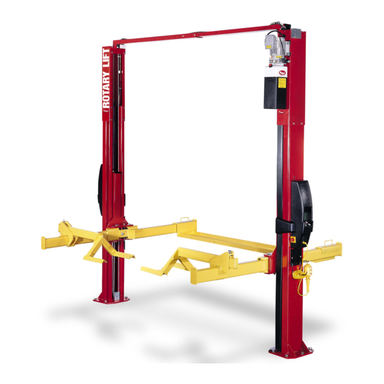
E, M, And i Series
(500 Series)
Two Post Surface Mounted Lifts
Capacity: 3,100kg (775 kg per arm)
Table of Contents
LP20198
O
O
P
P
E
E
R
R
A
A
T
T
I
I
O
O
N
N
&
&
TUV
TUV
Rheinland
M
M
A
A
I
I
N
N
T
T
E
E
N
N
A
A
N
N
C
C
E
E
M
M
A
A
N
N
U
U
A
A
L
L
OM20155
Rev. -- 1/6/2004
Advertisement

Related Manuals for Rotary i Series


Summary of Contents for Rotary i Series
- Page 1 Maintenance Instructions ..............8 Trouble Shooting ................9 Latch Cable Adjustment ..............18 Manual Lowering Instructions ............19 INSTALLER: Please return this booklet to literature package and give to lift owner/operator. LP20198 OM20155 © January 2004 by Rotary Lift. Rev. -- 1/6/2004...
- Page 2 Only those technicians who have been properly trained in the usage and care of the lift should be allowed to operate the lift. Local regulations MAY require that the trained operator be at least 18 years of age or be supervised by a trained operator while: A.
- Page 3 Lift Controls M Series Lifts Lift Controls 1 Turning Key to the right provides electricity to the motor. 2 Pushing button starts the motor and raises the arms. 3 Pulling handle down disengages safety latches. 4 Remove cap to fill or add fluid to power unit tank. 5 Turning Knob Lowers Lift.
- Page 4 Lift Controls For: E Series Lifts 1 Turning disconnect switches provides electircity to motor. Note: Both disconnect switches must be "ON" to provide electricity to motor. 2 Raises lift. 3 Lowers lift. 4 Resets the lift. 5 Lowers lift to locking latches.
- Page 5 OPERATING INSTRUCTIONS Surface Mounted Frame Engaging Lifts To avoid personal injury and/or property damage, permit only trained personnel to WARNING operate lift. After reviewing these instructions, get familiar with lift controls by running the lift through a few cycles before loading vehicle on lift. Always lift the vehicle using all lifting devices.
- Page 6 4. While Using Lift: 7 Unloading: • Avoid excessive rocking of vehicle while on lift. • Assure lift is fully lowered. • Avoid accidental touching of exposed exhaust system on • Retract forks as far as possible. raised vehicles. Watch for air hoses and electrical cords which may be tripped over.
- Page 7 • Replace all decals on the lift if unable to read or missing. Reorder labels from Rotary Lift. • Daily: Inspect lifting devices for damage or excessive wear. If parts are worn, call local service representative.
- Page 8 TROUBLE SHOOTING FOR OPERATORS FOR i SERIES LIFTS Up button pressed but lift doesn't raise Trouble Cause Remedy Error message on LCD. 1. Overhead Sensor Fault 1. Check sensor for contact with vehicle. No error message on LCD. 1. Touch pad not functioning. 1.
- Page 9 No error message on LCD 1.Touchpad not functioning column if neither touchpad is functioning contact service representative for further assis- tance. TROUBLE SHOOTING FOR OPERATORS FOR E SERIES LIFTS Up button pressed but lift doesn't raise Trouble Cause Remedy 9 signals.
- Page 10 TROUBLE SHOOTING FOR OPERATORS FOR E SERIES LIFTS Down button pressed but lift doesn't lower Trouble Cause Remedy 6 signals. 1. LOWERING VALVE CIRCUIT 1. Check lowering valve plug on FAULT power unit. If connection is good and you are still getting this error contact service representative for further assistance.
- Page 11 • If electrical problems develop, make repairs according to • Monthly: Lubricate locking latch shafts. Push latch local electrical codes. Use genuine Rotary Lift parts when replacement is necessary. handle several times for oil to penetrate joints. Annual Inspection (performed by Authorized Personnel) Aside from the routine checks that are stated under "Operator Maintenance", the following...
- Page 12 2. Cable is off sheaves. 2. Check position of upper sheaves. (M Series lifts only) 3. Latch cable is loose. 3. Replace cable. Note: Shim thickness of 51mm is possible by using optional shim kit #FC5393. Contact your authorized Rotary repair person.
- Page 13 TROUBLE SHOOTING FOR AUTHORIZED MAINTENANCE PERSONNEL FOR ALL Series Lifts Remedy Trouble Cause 1. Fill tank to MIN___ mark with Lift stops short of full rise or 1. Low oil level ISOVG32 hydraulic oil or chatters. DexronIII ATF. 2. Air in hydraulic lines/cylinder 2.
- Page 14 TROUBLE SHOOTING FOR AUTHORIZED MAINTENANCE PERSONNEL FOR i Series Lifts Down button pressed but lift doesn't raise Trouble Cause Remedy Error message on LCD 1. LOWERING VALVE CIRCUIT 1a. Replace lowering valve. FAULT 1b. Check lowering valve plug. 2. Faulty solenoid or faulty connec- 2.
- Page 15 TROUBLE SHOOTING FOR AUTHORIZED MAINTENANCE PERSONNEL FOR E Series Lifts Up button pressed but lift doesn't raise Trouble Cause Remedy 1. Check sensor for contact with 9 Signals. 1. OVERHEAD SENSOR HAS vehicle. BEEN TRIPPED 2. Power unit circuit fault 2.
- Page 16 TROUBLE SHOOTING FOR AUTHORIZED MAINTENANCE PERSONNEL FOR E Series Lifts Down button pressed but lift doesn't lower Remedy Trouble Cause 1. LOWERING VALVE CIRCUIT 1. Replace lowering valve. 6 Signals FAULT 2. Check lowering valve plug. 1. Latch Release Fault 1 7 Signals 1.
- Page 17 Latch Cable Adjustment For M Series Lifts Checking and Adjusting Equalizer Cables: Raise lift to check equalizer cable tension. Below carriage, grasp adjacent cables between thumb and forefinger, with about 67N effort you should just pull the cables together. Adjust at upper tie-offs (Fig. 5). Shoulder Bolt Upper Cable Tie Off &...
- Page 18 For E and i Lifts Only MANUAL LOWERING OF LIFT If your lift is in a raised position and you lose power it is important to know how to lower the lift manually. Make sure Lowering nothing is under the lift and all unautho- Valve rized personnel are away from the lift area.
- Page 19 EC Declaration of Conformity to Type Manufacturer’s Name ....Rotary Lift/Dover Corporation Manufacturer’s Address ....2700 Lanier Drive Madison, Indiana 47250 USA Representative’s Name ....John Uhl Representative’s Address ....Rotary Lift 2700 Lanier Drive Madison, Indiana 47250 USA Type of Equipment ....
- Page 20 Replacement Parts: See installers package for parts breakdown sheet. Order Genuine Rotary replacement parts from your nearest Authorized Parts Distributor. Maintenance Assistance: Contact your local Rotary distributor. Should further assistance be required, contact Rotary Lift, at one of the phone numbers listed below. World Headquarters: Italy:...
Need help?
Do you have a question about the i Series and is the answer not in the manual?
Questions and answers