Table of Contents
Advertisement
Quick Links
Advertisement
Table of Contents

Related Manuals for Carrier AquaForce PUREtec 30XW-PZE 1001


Summarization of Contents
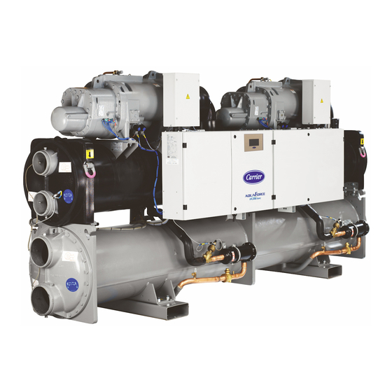
Introduction to Carrier Chillers
Installation Safety Considerations
Safety measures and precautions for unit installation.
Equipment and Components Under Pressure
Safety related to pressurized equipment and components.
Maintenance Safety Considerations
Safety precautions for maintenance activities.
Repair Safety Considerations
Safety guidelines for unit repair.
Preliminary Checks Before Operation
Check Equipment Received
Verifies the condition and completeness of the received unit.
Moving and Sitting the Unit
Instructions for safely moving and positioning the unit.
Dimensions and Clearances
30XW-PZE/30XWHPZE 301-651 Dimensions
Physical dimensions and clearance requirements for specific models.
30XW-PZE/30XWHPZE 801-1101 Dimensions
Physical dimensions and clearance for larger models.
Physical and Electrical Data
Physical Data Overview
Presents physical characteristics like sound levels and dimensions.
Electrical Data Overview
Contains electrical specifications, power, and current data.
Short-Circuit Stability Current
Information on short-circuit current capacity for unit protection.
Compressor Electrical Data
Detailed electrical specifications for compressors.
Compressor Usage per Circuit
Shows compressor assignment to circuits A and B.
Electrical Connection Guidelines
Power Supply Requirements
Requirements for the unit's power supply.
Voltage Phase Imbalance
Guidelines on acceptable voltage phase imbalance.
Power Connection and Disconnect Switch
Details on power connection and disconnect switch usage.
Recommended Wire Sections
Guidance on selecting appropriate wire sizes for connections.
Power Cable Entry
Instructions for routing power cables into the control box.
Field Control Wiring
Guidelines for making field connections for control wiring.
24V Power Reserve for User
Information on the 24V power reserve available for user wiring.
Application Data and Operating Limits
Operating Limits
Defines the operational boundaries for the unit.
Minimum Chilled Water Flow
Specifies the minimum required flow rate for chilled water.
Maximum Chilled Water Flow
Details the maximum allowable chilled water flow.
Condenser Water Flow Rate
Information on condenser water flow rates.
Water Passes Configuration
Describes the number of water passes in heat exchangers.
Evaporator and Condenser Water Flow Rate
Flow rate data for evaporator and condenser.
Variable Flow Evaporator
Details on using variable flow for the evaporator.
System Minimum Water Volume
Requirements for minimum water volume in the system.
Evaporator Pressure Drop Curves
Curves illustrating evaporator pressure drop.
Condenser Pressure Drop Curves
Curves illustrating condenser pressure drop.
Water Connections
Operating Precautions
Important precautions for water circuit connections.
Water Connections Details
Details on water connection types and diameters.
Flow Control
Information on flow control and pump interlock.
Water Box Bolt Tightening
Procedures for tightening water box bolts.
Master/Slave Unit Operation
How to operate units in a master/slave configuration.
Operating Modes for Heat Pump Units
Cooling Mode
Description of the unit's cooling operational mode.
Heating Mode
Description of the unit's heating operational mode.
High Condensing Option (Option 150)
Physical Data with Option 150
Physical data specific to units with the high condensing option.
Electrical Data with Option 150
Electrical data specific to units with the high condensing option.
Operating Limits with Option 150
Operating limits specific to units with the high condensing option.
Major System Components and Operation Data
Direct-Drive Twin-Screw Compressor
Details on the twin-screw compressor and its control.
Oil Filter
Information about the compressor's oil filter.
Refrigerant Types
Specifies the refrigerants used in the unit.
Lubricant Information
Details the approved lubricant for the compressor.
Oil Supply Solenoid Valve
Description of the oil supply solenoid valve.
Capacity Control System
Explains the system for controlling unit capacity.
Suction Valve (Option 92)
Information on the optional suction valve.
Pressure Vessels
General information and monitoring of pressure vessels.
Evaporator Details
Details on the evaporator design and specifications.
Condenser and Oil Separator
Information on the condenser and oil separator unit.
Economiser Function
Explanation of the economiser function.
Electrical Cabinet Air Pressurization Detection
How air pressurization in the electrical cabinet is detected.
Electronic Expansion Valve (EXV)
Details on the electronic expansion valve.
Moisture Indicator
Function and use of the moisture indicator.
Filter Drier
Role and maintenance of the filter drier.
Sensors Used
Information on the sensors used in the unit.
SRMCR High-Pressure Safety Circuit
Description of the SRMCR high-pressure safety circuit.
Safety Loop Function and Reset
Explains the function and reset procedure for the safety loop.
Restart After High Pressure Detection
Procedure for restarting after high pressure events.
Safety Accessory Failure Checks
Checks to perform if the safety accessory appears to fail.
Contactor Feedback Monitoring
How contactor feedbacks are used for safety monitoring.
Cross Circuit Detection
Functionality for detecting cross circuits in the safety loop.
Safety Loop State Diagram
State diagram illustrating the logic of the safety relay.
Safety LED Displays
Visual checks of safety relay status using LED displays.
Options and Accessories
Light-Brine Solution Option
Option for chilled brine production down to -3°C.
Master/Slave Operation
Allows two units to operate in parallel with time equalisation.
Single Power Connection Point
Unit power connection via a single main supply.
Evaporator Pump Power/Control Circuit
Electrical and control for one evaporator pump.
Evaporator Dual Pumps Power/Control Circuit
Electrical and control for two evaporator pumps.
Condenser Pump Power/Control Circuit
Electrical and control for one condenser pump.
Condenser Insulation
Thermal insulation for the condenser.
Service Valve Set
Valves for isolating refrigerant circuit components.
Evaporator One Pass Option
Evaporator with one pass on the water side.
Condenser One Pass Option
Condenser with one pass on the water side.
21 Bar Evaporator Option
Reinforced evaporator for higher service pressure.
21 Bar Condenser Option
Reinforced condenser for higher service pressure.
Reversed Evaporator Water Connections
Evaporator with reversed water inlet/outlet.
Reversed Condenser Water Connections
Condenser with reversed water inlet/outlet.
Lon Gateway Communication
Communication board for Lon Talk protocol.
BACnet Over IP Communication
Communication via BACnet protocol over Ethernet.
Modbus Over IP and RS485 Communication
Communication via Modbus protocol over Ethernet.
High Condensing Temperature Option
Optimized compressor for high condensing temperatures.
Condensing Temperature Limitation Option
Limits maximum condenser leaving water temperature.
Low Condensing Temperature Control
Controls low condenser temperature systems.
Dry-Cooler Control Option
Control adaptation for dry-coolers.
Energy Management Module
EMM board with additional inputs/outputs for remote control.
SmartVuT™ Control Interface
7-inch colour touch screen user interface.
Dual Relief Valves on 3-Way Valve
Three-way valve system for dual relief valves.
Swiss Regulations Compliance
Additional tests for water heat exchangers to meet Swiss regulations.
Russian Regulations Compliance
EAC certification for compliance with Russian regulations.
Australian Regulations Compliance
Unit approval to Australian code.
Low Noise Level Option
Evaporator sound insulation for lower noise.
Welded Evaporator Connection Kit
Victaulic piping connections with welded joints.
Welded Condenser Water Connection Kit
Victaulic piping connections with welded joints.
Flanged Evaporator Water Connection Kit
Victaulic piping connections with flanged joints.
Flanged Condenser Water Connection Kit
Victaulic piping connections with flanged joints.
Thermal Compressor Insulation
Insulation layer for the compressor.
Morocco Regulation Compliance
Specific documents for Morocco regulations.
Free-Cooling Dry-Cooler Control
Control for free-cooling dry-coolers.
Low GWP A1 R-515B Refrigerant
Unit delivered with R-515B refrigerant (A1, GWP 299).
Standard Maintenance Procedures
Maintenance Level Information
Classification of maintenance levels (1, 2, 3).
Level 1 Maintenance Tasks
Procedures for basic maintenance tasks by the operator.
Level 2 Maintenance Tasks
Procedures for maintenance requiring specialized skills.
Level 3 Maintenance Tasks
Advanced maintenance requiring manufacturer expertise.
Tightening Electrical Connections
Torque values for tightening main electrical connections.
Compressor Power Terminal Precautions
Precautions for connecting compressor power terminals.
Power Contactor Connection Precautions
Precautions for connecting power contactors.
Tightening Bolts and Screws
Torque specifications for main bolts and screws.
Evaporator and Condenser Maintenance
Maintenance checks for evaporator and condenser.
Oil Filter Change Schedule
Schedule and procedure for changing the oil filter.
Compressor Rotation Control
Procedures for controlling compressor rotation direction.
High Pressure Safety Loop Periodic Test
Periodic testing of the high-pressure safety loop.
Power Contactor Check Procedure
Procedure for checking power contactors.
Complete Safety Loop Test
Comprehensive test for the entire safety loop.
Final Shutdown Procedures
Shutting Down the Unit
Steps for safely shutting down the unit.
Recommendations for Disassembly
Guidelines for disassembling the unit.
Fluids to be Recovered for Treatment
Lists fluids that need recovery for treatment.
Materials for Recycling
Lists materials for recycling after disassembly.
Waste Electrical and Electronic Equipment (WEEE)
Procedures for handling WEEE.
Start-Up Checklist
Preliminary Information
Fields for basic job and unit identification.
Preliminary Equipment Check
Checks related to shipping damage and unit installation.
Unit Start-Up Checklist
Checklist items for the unit's initial start-up.
Cooler Water Loop Checks
Checks related to the cooler water loop.
Pressure Drop Check
Steps to check pressure drop across the cooler.
Appendices
Appendix 1: Declaration of Conformity
Document confirming product conformity.
Appendix 2: Wiring Diagram
Provides the electrical wiring diagram for the unit.
Appendix 3: Machine PID
Machine PID parameters.
Appendix 4: Dimensional Drawings
Drawings showing the unit's dimensions.
Need help?
Do you have a question about the AquaForce PUREtec 30XW-PZE 1001 and is the answer not in the manual?
Questions and answers