Table of Contents
Advertisement
Quick Links
Advertisement
Table of Contents

Related Manuals for LeCroy ZS1500


Summary of Contents for LeCroy ZS1500
- Page 1 ZS1000 High Impedance Active Probe Instruction Manual February 2007...
- Page 2 Spare parts, replacement parts and repairs are warranted for 90 days. In exercising its warranty, LeCroy, at its option, will either repair or replace any assembly returned within its warranty period to the Customer Service Department or an authorized service center. However, this will be done only if the product is determined by LeCroy’s examination to be defective due to workmanship or materi-...
- Page 3 Electrostatic Discharge EN 61000-4-3/A1:2003 RF Radiated Electromagnetic Field David C. Graef European Contact: Vice President & Chief Technology Officer Your local LeCroy Sales Office or Place: LeCroy Corporation LeCroy Europe GmbH 700 Chestnut Ridge Road Waldhofer Str 104 Chestnut Ridge, NY 10977...
- Page 4 BLANK PAGE ZS1000-OM-E Rev C...
-
Page 5: Table Of Contents
Operation Handling the Probe ............4-1 Connecting the Probe to the Test Instrument ....4-1 Connecting the Probe to the Test Circuit ......4-1 Operation with a LeCroy Oscilloscope ......4-1 High Frequency Measurements Input Loading ..............5-1 Inductive Loading (Lead Length) ........5-1 Capacitive Loading ............5-2 Care and Maintenance Cleaning ................6-1... - Page 6 ZS1000 High Impedance Active Probe Performance Verification Test Equipment Required ..........7-1 Preliminary Procedure ............7-2 Functional Check ..............7-3 Procedure .................7-4 A. Output Zero Voltage ..........7-4 B. LF Attenuation Accuracy...........7-4 Adjustment Procedure Introduction ...............8-1 Test Equipment Required ..........8-1 Preliminary Procedure ............8-2 Procedure .................8-3 A.
-
Page 7: Safety Information
Do not use the probe if any part is damaged. All maintenance should be referred to qualified service personnel. Avoid physical injury. The probe tips are extremely sharp. Use care when handling to prevent injury, including accidental skin puncture. 1–1 ZS1000-OM-E Rev C... -
Page 8: Conventions Used In This Manual
ZS1000 High Impedance Active Probe Use of the probe and or the test instrument it is connected to in a man- ner not specified by the manufacturer may impair the protection mecha- nisms. CONVENTIONS USED IN THIS MANUAL The following conventions may appear in this manual: Note A Note contains information relating to the use of the product. -
Page 9: Overview
Overview 2 Overview PRODUCT DESCRIPTION The 1 GHz ZS1000 is a small, high impedance active probe designed to meet today’s increasing demand for measurements on a variety of test points. With low input capacitance and high input resistance, circuit loading is minimized. -
Page 10: Standard Accessories
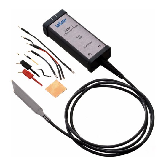
ZS1000 High Impedance Active Probe STANDARD ACCESSORIES The ZS1000 probe is shipped with the following standard accessories: Item: Quantity: Straight Tip Sprung Hook Right Angle Connector Offset Ground Ground Blade Copper Pad Short Single lead Long Single Lead Instruction Manual... -
Page 11: Features And Accessories
Features and Accessories 3 Features and Accessories The ZS1000 probe is provided with numerous features and accessories to make probing and connecting to different test points easier than ever. PROBE HEAD The small, low mass probe head is designed for ease of use and high performance. -
Page 12: Leads
ZS1000 High Impedance Active Probe IC Lead Tip Covered in insulation on all sides (except for a small edge), this tip was designed to prevent shorting neighbor- ing IC leads. The gold part of the tip is not insulated and should touch the IC lead to be tested. - Page 13 SMD ICs. Fits in either probe socket, or can be used with a lead. The Sprung Hook is a stan- dard accessory ZS1000 available black and red. PK-ZS-007R, PK-ZS-007B, package of 4 each 3–3 ZS1000-OM-E Rev C...
- Page 14 ZS1000 High Impedance Active Probe Ground Spring with Hook A flexible spring connected to a square pin that fits into either of the probe head sockets. Designed to be used as a ground lead, there is a hook on the end of the spring so that it can probe general circuits.
- Page 15 IC, and can then be sol- dered to the IC ground. The Copper Pad can also be used with the Offset Ground. PK-ZS-008, package of 4 PK-ZS-009, package of 4 3–5 ZS1000-OM-E Rev C...
- Page 16 ZS1000 High Impedance Active Probe C. Leads While longer leads provide greater flexibility when connecting the probe to a circuit, the added inductance may degrade the fidelity of high fre- quency signals. See Section 4 for additional information. Short and Long Lead...
-
Page 17: Operation
Using one of the available accessories makes the ZS1000 probe with its small profile and low mass head ideally suited for applications in dense circuitry. - Page 18 ZS1000 High Impedance Active Probe BLANK PAGE 4–2 ZS1000-OM-E Rev C...
-
Page 19: High Frequency Measurements
L or C from this circuit, the method to improve waveform fidelity is to raise the resonant frequency beyond the bandwidth of interest in the measurement. The resonant frequency of a simple LC circuit can be represented by: ------------------ Resonance 2π LC 5–1 ZS1000-OM-E Rev C... -
Page 20: Capacitive Loading
ZS1000 High Impedance Active Probe The resonant frequency of a series LC circuit can be raised by decreas- ing the inductance, capacitance or both. Since the input capacitance is already very low and cannot be reduced, you can only try to reduce the inductance. This can be accomplished by using the shortest possible input lead as well as the shortest possible ground lead. - Page 21 236 Ω, and at 1.0 GHz the reactance has been lowered to 177 Ω If, at a given frequency, the source impedance is large with respect to the input impedance, a measurable reduction in the output signal ampli- tude may occur. probe × ------------------------------------- - probe source 5–3 ZS1000-OM-E Rev C...
- Page 22 ZS1000 High Impedance Active Probe where: is the probe’s input impedance and probe is the source impedance source As an example: At 750 MHz, where the probe input impedance has reduced to 236 Ω, and a source resistance of 250 Ω the probe output amplitude is reduced ×...
-
Page 23: Care And Maintenance
Adjustment Procedures are included in this manual.) SERVICE STRATEGY The ZS1000 probe utilizes fine pitch surface mount devices. It is there- fore impractical to attempt to repair in the field. Defective probes must be returned to a LeCroy service facility for diagnosis and exchange. A defective probe under warranty will be replaced with a factory refur- bished probe. -
Page 24: Replacement Parts
RAN be clearly shown on the outside of the shipping pack- age for prompt redirection to the appropriate department. 1. Contact your local LeCroy sales or service representative to obtain a Return Authorization Number. 2. Remove all accessories from the probe. Do not include the manual. - Page 25 Care and Maintenance 6–3 ZS1000-OM-E Rev C...
- Page 26 ZS1000 High Impedance Active Probe Table 6-1: Replaceable Parts List Item LeCroy P/N Replacement Quantity Straight Tip PK-ZS-001 Offset Ground PK-ZS-002 Short Lead PK-ZS-003 Long Lead PK-ZS-004 Y Lead Adapter PK-ZS-005 Right Angle Connector PK-ZS-006 Sprung Hook - Red PK-ZS-007R...
-
Page 27: Performance Verification
This procedure can be used to verify the warranted characteristics of the ZS1000 High Impedance Active Probe. The recommended calibration interval for the model ZS1000 is one year. The complete performance verification procedure should be per- formed as the first step of annual calibration. Test results can be recorded on a photocopy of the Test Record provided in Appendix A at the end of the manual. -
Page 28: Preliminary Procedure
Pomona 5187-C-36 36" PRELIMINARY PROCEDURE 1. Connect the ZS1000 probe to the female end of the ProBus Exten- sion Cable. Connect the male end of the ProBus Extension Cable to channel 1 of the oscilloscope. 2. Turn the oscilloscope on and allow at least 30 minutes warm-up time for the ZS1000 and test equipment before performing the Verifica- tion Procedure. -
Page 29: Functional Check
Selecting File, Recall Setup... from the menu bar. b. Then touching the Recall Default button. 3. Touch the C1 trace label to open the C1 Vertical Adjust dialog. 4. Verify that the probe sensed (ZS1000) is displayed as a dialog tab. 7–3 ZS1000-OM-E Rev C... -
Page 30: Procedure
ZS1000 High Impedance Active Probe PROCEDURE A. Output Zero Voltage 1. Connect one end of a BNC cable to the female BNC connector on the probe end of the ProBus extender cable. Connect the precision 50 Ω terminator to the other end of the BNC cable. - Page 31 5. Set the DMM to read AC volt and set the range to measure 5.0 Vrms. 6. Set the mode of the function generator to sine wave, the frequency to 70 Hz and the output amplitude to 5 Vrms ±10 mV as measured on the DMM. 7–5 ZS1000-OM-E Rev C...
- Page 32 ZS1000 High Impedance Active Probe 7. Record the output voltage to 1 mV resolution as "Generator Output Voltage" in the Test Record. Be careful not to alter the output ampli- tude after the reading is recorded. 8. Divide the reading recorded in step B-7 by 10 and record the result with 100 µV resolution as "Expected Output Voltage, top range"...
- Page 33 24. Verify that the mid range gain error is less than ±1.0% This completes the Performance Verification of the ZS1000. Complete and file the Test Record, as required to support your internal calibration procedure. Apply suitable calibration label to the ZS1000 housing as required. 7–7 ZS1000-OM-E Rev C...
- Page 34 ZS1000 High Impedance Active Probe BLANK PAGE 7–8 ZS1000-OM-E Rev C...
-
Page 35: Adjustment Procedure
8 Adjustment Procedure INTRODUCTION You can use this procedure to adjust the ZS1000 probe to meet the war- ranted specifications. This procedure should only be performed if the probe fails to meet the Performance verification tests for Output Zero or Offset Accuracy. -
Page 36: Preliminary Procedure
2. Gently pull on the probe cable to slide the circuit board assembly from the metal housing. 3. Connect the ZS1000 probe to the female end of the ProBus exten- sion cable, being careful to line up all six pins of the probe connec- tor. -
Page 37: Procedure
Adjustment Procedure 4. Apply power to the oscilloscope and test equipment. 5. Allow at least 30 minutes warm-up time for the ZS1000 and test equipment before starting the calibration procedure. PROCEDURE A. Adjust Output Zero 1. Connect one end of a BNC cable to the probe end of the ProBus extension cable. -
Page 38: Verify Calibration
ZS1000 High Impedance Active Probe 7. Disconnect the probe from the ProBus extender and re-install the circuit board into the probe case, being careful to align the ProBus interface connector with the opening on the other end of the probe. -
Page 39: Specifications
Output Connector ProBus Interface ProBus Oscilloscope Full Compatibility LeCroy oscilloscope with firmware ver- sion 5.0.0.2 or later Subject to input voltage vs. frequency derating. See Figure 9-1. WARRANTED CHARACTERISTICS Warranted characteristics are parameters with guaranteed perfor- mance. Unless otherwise noted, tests are provided in the Performance Verification Procedure for all warranted specifications. -
Page 40: Environmental Characteristics
ZS1000 High Impedance Active Probe ENVIRONMENTAL CHARACTERISTICS Temperature, warranted 15 to 35 °C Temperature, operating 0 °C to 50 °C Temperature, non-operating -40 °C to 71 °C Relative Humidity 80% max. up to 31 °C, decreasing lin- early to 45% max. at 50 °C... -
Page 41: Compliance And Certifications
Part 031: Particular requirements for hand-held probe assemblies for elec- trical measurement and test. EMC Directive: EN 61326/A3:2003 EMC requirements for electrical equip- ment for measurement control and laboratory use. 9–3 ZS1000-OM-E Rev C... - Page 42 ZS1000 High Impedance Active Probe Electromagnetic Emissions: EN 55011/A2:2002 Class A Radiated Emissions. Electromagnetic Immunity: EN 61000-4-2/A2:2001 Electrostatic Discharge. (Air/Contact Discharge: 4 kV) EN 61000-4-3/A1:2003 RF Radiated Electromagnetic Field (80 MHz to 1 GHz; 3 V/m) Toxic or Hazardous Substances and Elements...
- Page 43 X: Indicates that this toxic or hazardous substance contained in at least one of the homogenous materials used for this part is above the limit requirement specified in SJ/T11363-2006. EFUP (Environmental Friendly Use Period) Use Conditions: refer to the environmental conditions stated in the specifications section of this Manual. 9–5 ZS1000-OM-E Rev C...
- Page 44 ZS1000 High Impedance Active Probe BLANK PAGE 9–6 ZS1000-OM-E Rev C...
-
Page 45: Performance Verification Test Record
PERFORMANCE VERIFICATION TEST RECORD This record can be used to record the results of measurements made during the performance verification of the ZS1000 High Impedance Active Probe. Photocopy this page and record the results on the copy. File the com- pleted record as required by applicable internal quality procedures. -
Page 46: Equipment Used
ZS1000 High Impedance Active Probe EQUIPMENT USED: MODEL SERIAL CALIBRATION NUMBER DUE DATE OSCILLOSCOPE DIGITAL MULTIMETER FUNCTION GENERATOR The function generator used in this Performance Verification Procedure is used for mak- ing relative measurements. The output of the generator is measured with a DMM or oscilloscope in this procedure. - Page 47 Appendix A Notes _______________________________________________________ _______________________________________________________ _______________________________________________________ _______________________________________________________ _______________________________________________________ _______________________________________________________ _______________________________________________________ _______________________________________________________ _______________________________________________________ _______________________________________________________ _______________________________________________________ _______________________________________________________ _______________________________________________________ _______________________________________________________ _______________________________________________________ _______________________________________________________ _______________________________________________________ _______________________________________________________ _______________________________________________________ _______________________________________________________ _______________________________________________________ _______________________________________________________ _______________________________________________________ _______________________________________________________ _______________________________________________________ _______________________________________________________ A–3 ZS1000-OM-E Rev C...
- Page 48 ZS1000 High Impedance Active Probe Notes _______________________________________________________ _______________________________________________________ _______________________________________________________ _______________________________________________________ _______________________________________________________ _______________________________________________________ _______________________________________________________ _______________________________________________________ _______________________________________________________ _______________________________________________________ _______________________________________________________ _______________________________________________________ _______________________________________________________ _______________________________________________________ _______________________________________________________ _______________________________________________________ _______________________________________________________ _______________________________________________________ _______________________________________________________ _______________________________________________________ _______________________________________________________ _______________________________________________________ _______________________________________________________ _______________________________________________________ _______________________________________________________ _______________________________________________________ A–4 ZS1000-OM-E Rev C...
Need help?
Do you have a question about the ZS1500 and is the answer not in the manual?
Questions and answers