Table of Contents
Advertisement
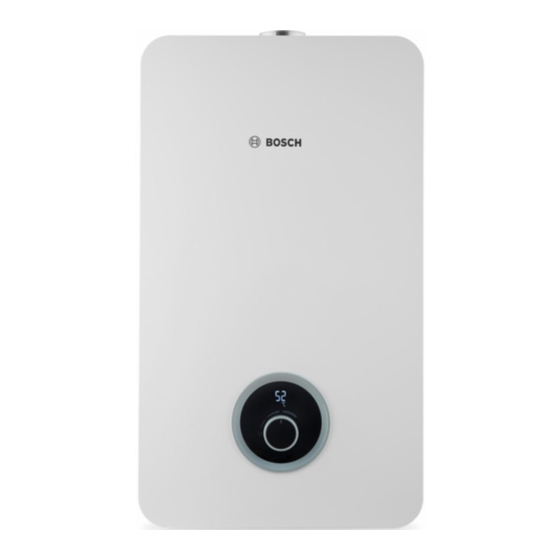
LOW NOX INSTANTANEOUS
GAS WATER HEATER
ROOM SEALED FAN ASSISTED / PRESSURIZED
GAS WATER HEATER
FOR INDOOR INSTALLATION
TRAINING AND SERVICE INFORMATION FOR AFTER SALES
This document is restricted to exclusive use by the official service partners. Each
country should adapt the manual and its contents to the available range.
Page 1 from 45
6 720 887 546 "SM FP_ErP LPP/MPP Europe 2018/05 en"
Advertisement
Table of Contents

Summarization of Contents
Appliance Description
Appliance Designation
Identifies main unit characteristics for reporting to service technicians or call centers.
Available Accessories
Lists optional accessories that can be added to the appliance.
Installation
Appliance Fixation on the Wall
Provides requisites and checklist for secure appliance wall mounting.
Water Connections
Checklist for ensuring correct and safe water connections to the appliance.
Gas Connection
Checklist for verifying the suitability and safety of the gas connection.
Flue Exhaustion
Procedure for configuring flue length parameters via HMI for specific models.
Appliance Performance
Guidance on measuring water flow and temperature increase for operational checks.
Components Overview
Internal Layout of T2400 / WD Versions
Diagram illustrating the internal components of T2400 and WD appliance versions.
Control Panel
Describes the function of the control panel for user, installer, and technician operations.
Control Panel HMI Overview WD-T2400 / T5600-T5700
Visual overview of the control panel Human Machine Interface for specific appliance models.
Display Symbols
Explanation of various symbols displayed on the appliance control panel and their meanings.
Heat Cell with Burner Pipes
Details the heat cell components including heat exchanger, burner, and electrodes.
Gas Manifold
Explains the gas manifold's role in gas distribution and burner design for NOx reduction.
Fan
Describes the fan's function, control, and types used in different appliance models.
Gas Valve
Explains the function of the modulating gas valve for controlling thermal load.
Gas Valve in LPP Version
Details the gas valve composition and safety elements in the LPP version.
Heat Exchanger
Describes the heat exchanger's configuration for heat transfer and its protection mechanisms.
Water Inlet Assy
Explains the water inlet assembly, including connection, filter, and flow restrictor.
Water Temperature Sensors
Details the NTC sensors used for measuring inlet and outlet water temperatures.
Box Temperature Sensor
Describes the NTC sensor for monitoring the temperature inside the appliance's sealed box.
Water Flow Sensor
Explains the turbine flow sensor, its operation, and characteristic curve.
Ignition Electrode
Details the ignition electrode's function in spark generation and safety time period.
Ionization Electrode
Explains the ionization electrode's role in sensing flame presence via ionization currents.
Working Principle / Electric Measurements
Water Flow Detection and Solar Mode Operation
Describes the water flow detection logic and conditions for solar mode operation.
Overview of ECU (Electronic Control Unit) MPP
Diagram showing the electronic control unit (ECU) and its connections for MPP models.
Overview of ECU (Electronic Control Unit) LPP
Diagram showing the electronic control unit (ECU) and its connections for LPP models.
Service
Procedure to Enter in Service Mode
Step-by-step guide on how to access the appliance's service mode using the menu.
Service Mode Parameters List (Technician Level)
Overview of parameters accessible to technicians within the service mode for adjustments.
P4 Diagnostic Mode Parameters List
List of parameters available in diagnostic mode (P4) for checking operational data and failures.
Gas Power Adjustment Parameters
Parameters for adjusting minimum/maximum power operation based on conditions like gas conversion.
Settings Parameters
Details on setting parameters for special features like connectivity and units.
P4
Describes accessing diagnostic mode (P4) for installer and technician checks.
Maintenance
Cleaning the Filter
Instructions for cleaning the water filter and heat exchanger assembly.
Trouble Shooting
Error Code Definition
Defines various error codes, their causes, and how they are resolved.


Need help?
Do you have a question about the T5600S 18 D 23 and is the answer not in the manual?
Questions and answers