Table of Contents
Advertisement
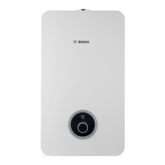
LOW NOX INSTANTANEOUS
GAS WATER HEATER
ROOM SEALED FAN ASSISTED / PRESSURIZED
GAS WATER HEATER
FOR INDOOR INSTALLATION
TRAINING AND SERVICE INFORMATION FOR AFTER SALES
This document is restricted to exclusive use by the official service partners. Each
country should adapt the manual and its contents to the available range.
Page 1 from 45
6 720 887 546 "SM FP_ErP LPP/MPP Europe 2018/05 en"
Advertisement
Table of Contents

Summarization of Contents
LOW NOX INSTANTANEOUS GAS WATER HEATER
Service & Training Information
Information for after-sales service and training for official service partners.
1. Introduction
2. Appliance Description
Overview of the LOW NOx gas water heater's features and capabilities.
2.1 Appliance Designation Explained
How to identify unit characteristics through specific model designation codes.
2.2 Available Accessories
Lists optional accessories available for purchase and use with the appliance.
3. Installation Procedures
3.1 Appliance Wall Fixation Checklist
Requirements and checklist for securely mounting the appliance on the wall.
3.2 & 3.3 Water & Gas Connections
3.4 Flue Exhaustion Configuration
Parameters for configuring flue length based on model and orientation for proper venting.
4. Components Overview
Internal Layout Diagram (T2400/WD)
Detailed diagram illustrating the internal layout and numbered components.
Control Panel HMI & Button Functions
Control Panel Button Operations
Description and functionality of each button on the control panel.
4.2 Heat Cell & Burner Assembly
Primary Air Plate Function
Details the primary air plate and its function in air/gas mixture for combustion.
4.3 Gas Manifold & Burner Design
Burner Design for NOx Reduction
Illustration and explanation of the rich and lean flame burner design for NOx emissions.
Gas Valve Safety & MPP Scheme
Gas Valve / Burner Scheme (MPP)
Schematic diagram of the gas valve and burner segments for MPP models.
5. Working Principle & Measurements
Water Flow Calculation Procedure
Step-by-step procedure for calculating water flow and its relation to burner operation.
6. Service Mode Access
Procedure to Enter Service Mode
Step-by-step instructions to access the appliance's service mode.
Gas Power Adjustment Parameters
Minimum Water Flow for P1 Operation
Minimum water flow requirements to maintain maximum power (P1) operation.
AA Mode Adjustments: Altitude, Power, Gas Type
Gas Type Definition by Switch (LPP)
How to define gas type using dip switches on LPP models.
Settings Parameters for Special Features
Diagnostic & Visualization Mode Access
How to access and use the diagnostic and data visualization modes.
Visualization Mode Parameters & Sensor Readings
Visualization of Last 10 Failures
Table showing the sequence and description of the last 10 recorded failures.
7. Maintenance Recommendations
Recommended Lubricants for Connections
Identification of recommended lubricants for appliance connections.
8. Trouble Shooting Guide
Troubleshooting Error Codes (A0-E2)
Covers error codes related to sensors, temperature protection, fan, flow, and exhaust.


Need help?
Do you have a question about the T5700S 18 D 23 and is the answer not in the manual?
Questions and answers