Table of Contents
Advertisement
Advertisement
Table of Contents

Subscribe to Our Youtube Channel
Related Manuals for Acer AC100


Summary of Contents for Acer AC100
- Page 1 AC100S Service Guide PART NO.: PRINTED IN TAIWAN...
-
Page 2: Revision History
Preface This Service Guide provides you with all technical information relating to the BASIC CONFIGURATION decided for Acer’s "global" product offering. To better fit local market requirements and enhance product competitiveness, your regional office MAY have decided to extend the functionality of a machine (e.g. add-on card, modem, or extra memory capability). - Page 3 Conventions The following conventions are used in this manual Denotes actual messages that Screen messages appear on screen. NOTE Gives bits and pieces of additional information related to the current topic. WARNING Alerts you to any damage that might result from doing or not doing specific actions.
-
Page 4: Preventing Electrostatic Discharge
Safety, Care and Regulatory Information Before installing a server, be sure that you understand the following warnings and cautions. WARNING: To reduce the risk of electric shock or damage to the equipment: Do not disable the power cord grounding plug. The grounding plug is an important safety feature. Plug the power cord into a grounded (earthed) electrical outlet that is easily accessible at all times. -
Page 5: Table Of Contents
Table of Contents System components System parts list ............2 Hardware specifications. - Page 6 Table of Contents Connecting the HDD Access LED cables ......60 Reinstalling the Fan ..........61 Reinstalling the Backplane Board .
-
Page 7: System Components
Chapter 1 System components Exploded view Chapter 1... -
Page 8: System Parts List
System parts list ACER_AC100S_W_HUNTER ISLAND Category Part Name Description Acer Part No. BOARDS BACKPLANE BOARD S15I BACKPLANE BOARD DIP 55.R3601.001 FRONT I/O BOARD AC100S(HUNTER ISLADN) 55.R7M01.001 FRONT I/O BOARD-1 TPM MODULE W/I STMICRO CHIP TPM MODULE, STMICRO PA.14000.052 TPM MODULE STMICRO SA19NP18ER28PVMK SA19NP18ER28PVMK (TPM FW:1.2.8.1C,TCG 1.2 REV.116,TXT... - Page 9 Category Part Name Description Acer Part No. HDD CARRIER ASSY HDD CARRIER HT-361D 60.R7M01.002 HEATSINK BRACKET ASSY BACK-PLATE 1156 AVC 60.R7M01.001 FAN DUCT COVER CVR FAN DUCT A HT-361D 42.R7M01.001 FRONT BEZEL W/KEY ASSY AT BEZEL HT-361D 60.R7M01.004 HOUSING W/HDD LED CABLE & ASSY HOUSING HT-361D 60.R7M01.005 FAN &...
- Page 10 Category Part Name Description Acer Part No. MAINBOARD MAINBOARD W/ INTEL C206 B3 AC100S(HUNTER)MB,W/PCH- MB.R7M01.001 STEPPING, W/O CPU/DIMM B3,W/O CPU/DIMM MEMORY MEMORY SAMSUNG UNB-DIMM DIMM 2G M391B5673EH1-CH9 KN.2GB0B.015 DDR3 1333MHZ 2GB M391B5673EH1-CH9 MEMORY NANYA UNB-DIMM DDR3 DIMM 2G NT2GC72B89B0NF- KN.2GB03.024 1333MHZ 2GB NT2GC72B89B0NF- CG DDR3 UNB MEMORY NANYA UNB-DIMM DDR3...
-
Page 11: Hardware Specifications
Chapter 2 System specifications Hardware specifications Items Specifications Processor socket LGA1155 Processor support Intel E3-1260L • Intel i3-2120 • Intel i3-2100 • Intel Pentium G850 • Intel Pentium G840 • Intel Pentium G620 • Core logic chipsets PCH Cougar Point C206 Networking One Gigabit Ethernet LAN port (RJ-45) Media storage... -
Page 12: Environmental Specifications
Environmental specifications Specifications Value Temperature range Operating 10°C to 35°C (50°F to 95°F) Non-operating -40° - 70° C (-40° - 158° F) Humidity (non-condensing) Operating 8 to 90% RH (non-condensing) Non-operating 5% to 95% RH (non-condensing) Mechanical specifications Specifications Value Dimensions (WxHxD) 210 mm (8.3”) x 267mm (10.5”) x 260 mm (10.2”) Weight... -
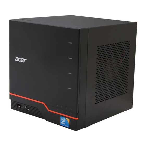
Page 13: System Appearance
Chapter 3 System appearance Front panel Icon Component USB 2.0 port Network indicator Hard disk drive (HDD) status indicator System status indicator Power indicator Individual HDD status indicators Chapter 3... -
Page 14: Front Inner View
Front inner view Icon Component Lock HDD carriers Power button Chapter 3... -
Page 15: Rear Panel
Rear panel Icon Component Recovery/reset button Video port LAN port USB 2.0 ports eSATA port Power connector Chapter 3... -
Page 16: Internal Components
Internal components Component Backplane board Power supply Memory module Mainboard System Fan Chapter 3... -
Page 17: System Led Indicators
System LED Indicators Front panel This section describes the different system LED indicators. LED indicator Color LED status Description Network White Link between system and network Random blink Network access or activity None Network disconnected HDD access White Blink HDD access None No HDD activity System status... -
Page 18: Rear Panel
LED indicator Color LED status Description Power White System is connected to the power supply and turned on and ready for use. Random blink • System is booting • System is in S3 sleep state (suspend to memory) None • System is not powered on. -
Page 19: System Block Diagram
System block diagram Chapter 3... - Page 20 Chapter 3...
-
Page 21: Mainboard
Chapter 4 Mainboard Mainboard connectors Label Description Label Description Backplane LED cable connector CN14 Front I/O board connector ATXCN2 4-pin power cable connector PCIE1 PCIE expansion slot CPU1 CPU socket BUZZER1 Buzzer HDD access LED cable connector CN16 SATA cable connector Vcore power F/W update (reserved) BAT1 Battery holder... -
Page 22: System Jumpers And Switch
System Jumpers and Switch Location Name Settings Clear CMOS Jumper 1-2 Normal (default) 2-3 Clear CMOS Power button connector Reset Jumper Open (default) Intrusion switch connector ME Update Jumper Open (default) Close ME update Chapter 4... -
Page 23: Hardware Removal And Installation
Chapter 5 Hardware removal and installation This chapter contains step-by-step procedures on how to disassemble this system for maintenance and troubleshooting. Disassembly Requirements To disassemble the computer, you need the following tools: Wrist grounding strap and conductive mat for preventing electrostatic discharge •... -
Page 24: Disassembly Procedure
Disassembly Procedure Removing the Hard Disk Turn the key to the unlock position and open the front panel door. Press to release the hard drive carrier handle. Chapter 5... - Page 25 Slide the hard drive carrier out of the HDD bay. Remove the carrier by gently prying open the right rail of the carrier (1) and lift the hard disk off the carrier (2) . Repeat the steps above to remove all hard disk drives and carriers. Chapter 5...
-
Page 26: Removing The System Cover
Removing the System Cover Perform the pre-disassembly procedure described on 17. Remove the three screws that secure system cover. Screw (Quantity) Color Torque Part No. M3-0.5*4 NI (3) Chrome 5.1 to 6.9 kgf-cm 86.1A524.4R0 Slide the system cover toward the back of the chassis until the tabs on the cover disengage with the slots on the chassis. -
Page 27: Removing The Front Bezel
Removing the Front Bezel Remove the system cover. Refer to the previous section for instructions. Release the left front bezel retention tabs from the chassis interior. Release the right front bezel retention tabs from the chassis interior. Chapter 5... -
Page 28: Removing The Backplane Board
Pull the bezel away from the chassis. Removing the Backplane Board NOTE: The photos of the backplane board in this section represents a sample only. Actual board may differ from photo. See “Removing the Hard Disk” on page 18. See “Removing the System Cover” on page 20. Disconnect the fan (1), LED (2), and power (3) cables from their backplane board connectors. - Page 29 Press the clip on the SATA cable (1) and pull up to disconnect (2) from its mainboard connector (CN16). Pull the backplane board bracket out of the chassis. Chapter 5...
- Page 30 Detach the four HDD SATA cables from their backplane board connectors. Remove the seven screws that secure the backplane board. Screw (Quantity) Color Torque Part No. M3 x L4 (7) Chrome 5.1 to 6.9 kgf-cm 86.19534.4R0 Chapter 5...
-
Page 31: Removing The Fan
Lift the backplane board off the bracket. Note:Circuit boards >10 cm2 has been highlighted with the yellow rectangle as above image shows. Please detach the Circuit boards and follow local regulations for disposal. Removing the Fan See “Removing the Hard Disk” on page 18. See “Removing the System Cover”... - Page 32 Pull the fan cable connector out through the chassis opening. Remove the four screws that secure the fan to the chassis. Screw (Quantity) Color Torque Part No. M3-0.5*4 NI (4) Chrome 5.1 to 6.9 kgf-cm 86.1A524.4R0 Chapter 5...
-
Page 33: Removing The Hdd Access Led Cables
Remove the fan. Removing the HDD Access LED cables See “Removing the Hard Disk” on page 18. See “Removing the System Cover” on page 20. See “Removing the Front Bezel” on page 21. See “Removing the Backplane Board” on page 22. See “Removing the Fan”... -
Page 34: Removing The Power Supply
Carefully pull out the HDD access LED cables, then detach the cable module. Removing the Power Supply See “Removing the Hard Disk” on page 18. See “Removing the System Cover” on page 20. See “Removing the Backplane Board” on page 22. Pull the cable tie to dislodge from the locking tab (1). - Page 35 While pressing the tab (1) on the 4-pin power cable, pull the cable off (2) the mainboard connector (ATXCN2). With the thumb in the thumb hole, press the tab (1) to release the mainboard tray (2) from the chassis. Chapter 5...
- Page 36 Slide the mainboard tray out slightly, until you have access to the power cable. While pressing the tab (1) on the 24-pin power cable, pull the cable off (2) the mainboard connector. Chapter 5...
- Page 37 Pull the power cable connectors out through the chassis openings. 10. Remove the four screws that secure the power supply. Screw (Quantity) Color Torque Part No. #6-32*3/16" NI Chrome 86.4A5A6.012 Chapter 5...
-
Page 38: Removing The Mainboard Tray
11. Push the power supply toward the front of the chassis and then remove it from the chassis. Removing the Mainboard Tray See “Removing the Hard Disk” on page 18. See “Removing the System Cover” on page 20. See “Removing the Front Bezel” on page 21. See “Removing the Backplane Board”... - Page 39 10. Disconnect the intrusion switch cable connector from its mainboard connector (JP6). 11. Disconnect the VGA cable connector from its mainboard connector (CN4). Chapter 5...
- Page 40 12. Pull out the mainboard tray completely. Chapter 5...
-
Page 41: Removing The Heatsink
Removing the Heatsink See “Removing the Mainboard Tray” on page 32. Use a screwdriver to loosen the four screws on the heatsink as shown below. Lift the heatsink away from the mainboard. Chapter 5... -
Page 42: Removing The Processor
Removing the Processor IMPORTANT: Before removing a processor from the mainboard, make sure to create a backup file of all important data. WARNING:The processor becomes very hot when the system is on. Allow it to cool off first before handling. See “Removing the Mainboard Tray”... - Page 43 Gently lift the processor out of its socket. IMPORTANT:If you are going to install a new processor, note the arrow on the corner to make sure the processor is properly oriented over the socket. Chapter 5...
-
Page 44: Removing The Memory Modules
Removing the Memory Modules See “Removing the Mainboard Tray” on page 32. Press the holding clips on both sides of the DIMM slot outward to release the DIMM (1). Gently pull the DIMM upward to remove it from the DIMM slot (2). If there is a second memory module installed, repeat steps 12 and 13 to remove it. - Page 45 Disconnect the power button cable connector from its mainboard connector (JP3). Remove the four screws that secure the mainboard. Screw (Quantity) Color Torque Part No. M3 x L4 (4) Chrome 5.1 to 6.9 kgf-cm 86.19534.4R0 Chapter 5...
-
Page 46: Removing The Rtc Battery
Lift the mainboard off the mainboard tray. Note:Circuit boards >10 cm2 has been highlighted with the yellow rectangle as above image shows. Please detach the Circuit boards and follow local regulations for disposal. Removing the RTC Battery See “Removing the Mainboard” on page 38. Remove the RTC battery. -
Page 47: Removing The Expansion Slot Cover
Removing the Expansion Slot Cover Use a screwdriver to loosen the screw that secures the slot cover lock to the expansion card or slot cover. Rotate the slot cover lock counterclockwise. Screw (Quantity) Color Torque Part No. M3-0.5*4 NI (1) Chrome 5.1 to 6.9 kgf-cm 86.1A524.4R0... - Page 48 Remove the one screw that secures the front I/O board bracket to the mainboard tray. Screw (Quantity) Color Torque Part No. M3-0.5*4 NI (1) Chrome 5.1 to 6.9 kgf-cm 86.1A524.4R0 Slide the front I/O board bracket slightly to the left to release its tabs from the mainboard tray notches. Lift to detach the front I/O board bracket.
-
Page 49: Removing The Power Button Cable Module
Remove the front I/O board. Note:Circuit boards >10 cm2 has been highlighted with the yellow rectangle as above image shows. Please detach the Circuit boards and follow local regulations for disposal. Removing the Power Button Cable Module See “Removing the Front I/O Board” on page 41. Loosen the screws that secure the power button cable module to the mainboard tray. - Page 50 Pull the power button cable module through the opening on the mainboard tray. Chapter 5...
-
Page 51: Reassembly Procedure
Reassembly Procedure Replacing the Power Button Cable Module Insert the power button cable module through the opening on the mainboard tray. Secure the power button cable module to the mainboard trayt using two screws. Screw (Quantity) Color Torque Part No. M1.6 x L6 (2) Chrome 86.1A56P.6R0... -
Page 52: Installing The Front I/O Board
Installing the Front I/O Board Insert the front I/O board into the bracket. Use three screws to secure the front I/O board to the bracket. Screw (Quantity) Color Torque Part No. M3 x L4 (3) Chrome 5.1 to 6.9 kgf-cm 86.19534.4R0 Make sure the tabs on the front I/O board bracket are inserted into the mainboard tray notches (1). - Page 53 Slide the front I/O board bracket slightly to the right and make sure that it is securely attached to the mainboard tray. Secure the front I/O board bracket to the mainboard tray with one screw. Screw (Quantity) Color Torque Part No. M3-0.5*4 NI (1) Chrome 5.1 to 6.9 kgf-cm...
-
Page 54: Reinstalling The Expansion Slot Cover
Connect the 26-pin cable connector to its front I/O board connector (CN1). Reinstalling the Expansion Slot Cover Insert the expansion card or slot cover. Rotate the slot cover lock clockwise. Secure the slot cover lock to the expansion card or slot cover using one screw. -
Page 55: Replacing The Rtc Battery
Replacing the RTC Battery Insert the RTC battery into the battery holder. Replacing the Mainboard Insert the mainboard into the mainboard tray. Chapter 5... - Page 56 Secure the mainboard to the mainboard tray using four screws. Screw (Quantity) Color Torque Part No. M3 x L4 (4) Chrome 5.1 to 6.9 kgf-cm 86.19534.4R0 Connect the power button cable connector to its mainboard connector (JP3). Chapter 5...
-
Page 57: Installing The Memory Modules
Disconnect the front I/O cable connectors to its mainboard connectors (CN14 and CN15). Installing the Memory Modules Insert the memory module into DIMM1A slot (1) and then press it down until it clicks into place (2). If a second memory module is available, install it in DIMM2A slot by repeating step 1. Chapter 5... -
Page 58: Reinstalling The Processor
Reinstalling the Processor IMPORTANT:IWhen installing a new processor, note the arrow on the corner to make sure the processor is properly oriented over the socket. Hold the processor by its edges. Insert the processor into the processor socket. Close the retention plate. Chapter 5... -
Page 59: Reinstalling The Heatsink
Press the load lever (1) and engage the load lever back into place. (2). Apply the thermal interface material. Use an alcohol pad to wipe off the old thermal grease from the heat sink and the processor socket retention plate. Apply a thin layer of an approved thermal interface material before installing the heatsink. -
Page 60: Reinstalling The Mainboard Tray
Use a screwdriver to tighten the four screws on the heatsink as shown below. Reinstalling the Mainboard Tray Push the mainboard tray into the chassis. Chapter 5... - Page 61 Connect the VGA cable connector to its mainboard connector (CN4). Connect the intrusion switch cable connector to its mainboard connector (JP6). Chapter 5...
-
Page 62: Reinstalling The Power Supply
Connect the backplane LED cable connector to its mainboard connector (CN3). Reinstalling the Power Supply Push the power cable connectors into the chassis openings. Chapter 5... - Page 63 Connect the 4-pin power cable connector to its mainboard connector (ATXCN2). Slide the mainboard tray out slightly, until you have access to the power cable connector. Chapter 5...
- Page 64 Connect the 24-pin power cable to its mainboard connector (ATXCN1). Slide the power supply into the chassis. Chapter 5...
- Page 65 Secure the power supply to the chassis using four screws. Screw (Quantity) Color Torque Part No. #6-32*3/16" (4) Chrome 5.1 to 6.9 kgf-cm 86.4A5A6.012 Push the mainboard tray into the chassis. Chapter 5...
-
Page 66: Connecting The Hdd Access Led Cables
Arrange the cables properly. Insert the cable tie through the guide (1). Make sure the cables are securely fastened by lodging the tie to the locking tab (2). Connecting the HDD Access LED cables Carefully insert the HDD access LED cables. Chapter 5... -
Page 67: Reinstalling The Fan
Connect the HDD access LED cable connector to its mainboard connector (CN2). Reinstalling the Fan Insert the fan into the chassis, making sure that the screw holes on the fan are aligned with those on the chassis. Chapter 5... - Page 68 Use four screws to secure the fan to the chassis. Screw (Quantity) Color Torque Part No. M3-0.5*4 NI (4) Chrome 5.1 to 6.9 kgf-cm 86.1A524.4R0 Push the fan cable connector through the chassis opening. Chapter 5...
-
Page 69: Reinstalling The Backplane Board
Push the backplane board LED cable connector through the chassis opening. Reinstalling the Backplane Board NOTE: The photos of the backplane board in this section represents a sample only. Actual board may differ from photo. Install the backplane board into the bracket. Chapter 5... - Page 70 Use seven screws to secure the backplane board to the bracket. Screw (Quantity) Color Torque Part No. M3 x L4 (7) Chrome 5.1 to 6.9 kgf-cm 86.19534.4R0 Connect the four HDD SATA cables to their backplane board connectors. Chapter 5...
- Page 71 Insert the backplane board bracket into the chassis. Push the backplane cable connector through the chassis opening. Connect the SATA cable connector to its mainboard connector (CN16). Chapter 5...
-
Page 72: Reinstalling The Front Bezel
Connect the fan (1), LED (2), and power (3) cables to their backplane board connectors. Reinstalling the Front Bezel Align the right front bezel retention tabs with the notches on the chassis interior. Close the right front bezel. Chapter 5... -
Page 73: Reinstalling The System Cover
Close the left front bezel. Make sure the left front bezel retention tabs clicks into the notches on the chassis interior. Reinstalling the System Cover Position and lower the system cover over chassis until it is complete aligned with the bottom. Push the cover towards the front until it is completely closed. -
Page 74: Reinstalling The Hard Disk
Use three screws to secure system cover to the chassis. Screw (Quantity) Color Torque Part No. M3-0.5*4 NI (3) Chrome 5.1 to 6.9 kgf-cm 86.1A524.4R0 Reinstalling the Hard Disk Align the rivets on the left rail of the carrier with the holes on the hard disk. . Chapter 5... - Page 75 Gently pry open the left rail of the carrier (1) and insert the hard disk into the carrier (2) . Close the hard disk carrier handle. Chapter 5...
- Page 76 Turn the key to the unlock position and open the front panel door. Insert the hard disk drive carrier, making sure that the hard disk SATA connector is properly inserted into the SATA connector on the backplane board. Insert all hard disk carriers. Chapter 5...
- Page 77 Close the front panel door. Chapter 5...
- Page 78 Chapter 5...
-
Page 79: System Diagnostics
Chapter 6 System diagnostics Hardware Diagnostic Procedure The system’s diagnostic function monitors system activity and performs IMPORTANT:The diagnostic tests described in this chapter are only intended to test Acer products. Non-Acer products, prototype cards, or modified options can give false errors and invalid system responses. -
Page 80: System Check Procedures
System Check Procedures Power system check If the system will power on, skip this section. Refer to System External Inspection. If the system will not power on, check if the power cable is properly connected to the system and AC source. System external inspection Inspect the LED indicators on the front panel, which can indicate the malfunction. -
Page 81: System Diagnosis
System Diagnosis Hardware diagnostic program The purpose of the hardware diagnostic program is to check hardware problems. It executes simple tests of each hardware component to make sure the hardware is not the source of the problem. If hardware problems, such as a fan, LED board, hard disk drive, memory;... - Page 82 Boot from HDD 0 HDD 1 HDD 2 HDD 3 HDD 0 HDD 1 HDD 2 HDD 3 USB disk Backplane board temperature check PQAF system test PQAF memory test PQAF HDD test Read SN from DMI data check End test After the diagnostic routine is completed, the HDD status indicator lights purple indicating the system has passed all diagnostic tests.
-
Page 83: System Status Error Codes
The lower nibble 'Y' indicates the BUS on which the different routines are being executed. 'Y' can be from 0 to 5. 0 = Generic DIM (Device Initialization Manager). 1 = On-board System devices. 2 = ISA devices. 3 = EISA devices. 4 = ISA PnP devices. -
Page 84: Clearing Cmos
If the system has not crashed or if you want to revert BIOS to previous settings: • During POST, press <Ctrl> + <Home> during POST. This action will flash the BIOS from the USB storage device to the system and reboot automatically after the flash update is completed. Remove the BIOS Recovery disk. -
Page 85: Bios Setup
Chapter 7 BIOS Setup BIOS setup is a hardware configuration program built into the system's Basic Input/Output System (BIOS). Since most systems are already properly configured and optimized, there is no need to run this utility. You will need to run this utility under the following conditions. •... -
Page 86: Entering The Bios Setup Utility
Entering the BIOS Setup Utility Turn on the computer and the monitor. If the computer is already turned on, close all open applications, then restart the computer. During POST, press <F2>. If you fail to press <F2> before POST is completed, you will need to restart the system. The Setup Main menu will be displayed showing the Setup’s menu bar. -
Page 87: Setup Utility Menus
Setup Utility Menus The Setup Main menu includes the following main setup categories. • Main • Advanced • Security • Server Mgnt • Boot Options • Boot Manager • Save & Exit In the descriptive table following each of the menu screenshots, settings in boldface are the default and suggested settings. -
Page 88: Main
Main The Main menu displays basic information about the system and lets you set the system date and time. Parameter Description System BIOS Version Version number of the BIOS setup utility. Build Date Date when the BIOS setup utility was built. Processor Type of CPU installed on the system. -
Page 89: Advanced
Advanced The Advanced menu display submenu options for configuring the function of various hardware components. Select a submenu item, then press <Enter> to access the related submenu screen. The items with a triangle beside them are sub-menus that can be accessed by highlighting the item and pressing <E >. - Page 90 the processor's type, frequency, core count and Cache L1, L2 settings. Memory Configuration This submenu displays the type and size of the memory installed in the system. Chipset Configuration Chapter 7...
-
Page 91: Acpi Configuration
This submenu is used to configure the Intel VT-d Technology and Intel TXT Technology. Parameter Description Option Intel VT-d Technology Enables or disables the Intel VT-d Technology. Enabled Disabled Intel TXT Technology Enables or disables the Intel TXT (LT) support. Enabled Disabled ME Subsystem... -
Page 92: Sata Configuration
SATA Configuration When this submenu is selected, the BIOS automatically detects the presence of SATA devices and displays the following items. Parameter Description Option Onboard SATA Controller Enables or disables the onboard SATA controller. Enabled Disabled SATA Mode Sets the SATA mode. IDE Mode ACHI Mode RAID Mode... -
Page 93: Usb Configuration
Parameter Description Option Onboard Graphics Enables or disables the onboard graphics controller. Enabled Controller Disabled Primary Graphics Sets the primary graphics to add-on or onboard. ADD ON Onboard Onboard LAN Controller Enables or disables the onboard LAN controller. Enabled Disabled Onboard LAN I/O ROM Enables or disables the onboard LAN I/O ROM. -
Page 94: Power Configuration
Power Configuration Parameter Description Option Deep Power Off Mode Enables or disables Eut Lot 6 support. Enabled Disabled Power On by RTC Alarm Use this feature to set an event using the Real Time Clock (RTC) to Enabled wake up the system at a specified time. Disabled If this item is set to Enabled, the following items will display. -
Page 95: Hardware Monitor
Hardware Monitor This submenu lets you monitor the parameters for critical voltages, temperatures and fan speeds. Chapter 7... -
Page 96: Security
Security The BIOS provides an Administrator and a User password. If you use both passwords, the Administrator password must be set first. Parameter Description Option Administrator Password This item indicates if an Administrator password has been entered for the system. "Not Installed"... -
Page 97: Server Mgm
Server Mgmt System Information This submenu displays the following product information. • System Product Name • System Serial Number • Base Board Product Name • Base Board Serial Number • UUID • NIC1 Mac Address -The BIOS will automatically enter the Mac address of this machine; however it may be over-ridden. -
Page 98: Boot Options
Event Log Configuration Change SMBIOS Event Log Settings Parameter Description Option Erase Event Log Choose options for erasing SMBIOS Event Log. Erasing is done prior to any logging activation during reset. Yes, Every reset Yes, Next reset When Log is Full Choose what to do when the SMBIOS Event Log is full. -
Page 99: Boot Manager
Parameter Description Option BIOS Watchdog Timer Enables or disables the BIOS Watchdog Timer. 5 min 10 min 15 min 20 min Set Boot Priority This feature allows you to specify the sequence of priority for the boot device. Boot Option #1~5. Options are UEFI, Network:, Removable, Optical Disk, Hard Disk UEFI Device Order This feature allows you to specify the boot sequence from all available Press <Enter>... - Page 100 Save & Exit The Save & Exit menu lists options for quitting the Setup Utility. Highlight any of the exit options, then press <Enter>. Parameter Description Save Changes and Exit Saves changes made and exit system setup. Discard Changes and Exit Discards changes made and exit system setup.
-
Page 101: Bios Post Codes And Messages
Chapter 8 BIOS POST codes and messages BIOS POST Messages During the Power-On Self-Test (POST), the BIOS will check for problems. If a problem is found, the BIOS will activate an alarm or display a message. The following is a list of such BIOS messages. POST Code Checkpoints The Power-On Self Test (POST) is a BIOS procedure that boots the system, initializes and diagnoses the system components, and controls the operation of the power-on password option. -
Page 102: Post Code Checkpoints List
POST code checkpoints list Bootblock initialization code checkpoint The following table describes the Award common tasks carried out by POST. An unique checkpoint number denotes each task. . Checkpoint Description Before D1 Early chipset initialization is done. Early super I/O initialization is done including RTC and keyboard controller. - Page 103 Bootblock recovery code checkpoints The Bootblock recovery code gets control when the BIOS determines that a BIOS recovery needs to occur because the user has forced the update or the BIOS checksum is corrupt. The following table describes the type of checkpoints that may occur during the Bootblock recovery portion of the BIOS: Checkpoint Description Initialize the floppy controller in the super I/O.
- Page 104 Checkpoint Description Initializes the CPU. The BAT test is being done on KBC. Program the keyboard controller command byte is being done after Auto detection of KB/MS using AMI KB-5. Initializes the 8042 compatible Key Board Controller. Detects the presence of PS/2 mouse. Detects the presence of Keyboard in KBC port.
- Page 105 Checkpoint Description Check boot password if installed. Clean-up work needed before booting to OS. Takes care of runtime image preparation for different BIOS modules. Fill the free area in F000h segment with 0FFh. Initializes the Microsoft IRQ Routing Table. Prepares the runtime language module. Disables the system configuration display if needed.
-
Page 106: Bios Post Codes
BIOS POST Codes This section lists the POST (Power-On Self-Test) codes for the AMI BIOS. POST codes are divided into two categories: recoverable and terminal. Recoverable POST Errors When a recoverable type of error occurs during POST, the BIOS will display an POST code that describes the problem. - Page 107 Post Code Description 1-3-1-1 Test DRAM refresh 1-3-1-3 Test 8742 Keyboard Controller Auto size DRAM Initialize POST Memory Manager Clear 512 kB base RAM 1-3-4-1 RAM failure on address line xxxx* 1-3-4-3 RAM failure on data bits xxxx* of low byte of memory bus Enable cache before system BIOS shadow Test CPU bus-clock frequency Initialize Phoenix Dispatch Manager...
- Page 108 Post Code Description 2-2-3-1 Test for unexpected interrupts Initialize POST display service Display prompt “Press F2 to enter SETUP” Disable CPU cache Test RAM between 512 and 640 kB Test extended memory Test extended memory address lines Jump to UserPatch1 Configure advanced cache registers Initialize Multi Processor APIC Enable external and CPU caches...
- Page 109 Post Code Description Initialize Extended BIOS Data Area Test and initialize PS/2 mouse Initialize floppy controller Determine number of ATA drives (optional) Initialize hard-disk controllers Initialize local-bus hard-disk controllers Jump to UserPatch2 Build MPTABLE for multi-processor boards Install CD ROM for boot Clear huge ES segment register 1-2 Search for option ROMs.
- Page 110 Post Code Description Initialize SMBIOS Initialize PnP Option ROMs Clear parity checkers Display MultiBoot menu Clear screen (optional) Check virus and backup reminders Try to boot with INT 19 Initialize POST Error Manager (PEM) Initialize error logging Initialize error display function Initialize system error handler PnPnd dual CMOS (optional) Initialize note dock (optional)
- Page 111 Post Code Description Go to BIOS Set Huge Segment Initialize Multi Processor Initialize OEM special code Initialize PIC and DMA Initialize Memory type Initialize Memory size Shadow Boot Block System memory test Initialize interrupt vectors Initialize Run Time Clock Initialize video Initialize System Management Manager Output one beep Clear Huge Segment...
- Page 112 Chapter 8...
Need help?
Do you have a question about the AC100 and is the answer not in the manual?
Questions and answers