Table of Contents
Advertisement
Advertisement
Table of Contents

Related Manuals for Acer AR585 F1


Summary of Contents for Acer AR585 F1
- Page 1 AR585 Series User Guide...
- Page 2 © 2010. All Rights Reserved. Acer AR585 Series User Guide Acer AR585 Model Number : Serial Number: Purchase Date: Place of Purchase:...
-
Page 3: Safety Instructions
Information for your safety and comfort Safety instructions Read these instructions carefully. Keep this document for future reference. Follow all warnings and instructions marked on the product. Turning the product off before cleaning Unplug this product from the wall outlet before cleaning. Do not use liquid cleaners or aerosol cleaners. -
Page 4: Using Electrical Power
• Never push objects of any kind into this product through cabinet slots as they may touch dangerous voltage points or short-out parts that could result in a fire or electric shock. Never spill liquid of any kind onto or into the product. -
Page 5: Product Servicing
• Use the product only with the supplied power supply cord set. If you need to replace the power cord set, make sure that the new power cord meets the following requirements: detachable type, UL listed/CSA certified, VDE approved or its equivalent, 4.6 meters (15 feet) maximum length. Product servicing Do not attempt to service this product yourself, as opening or removing covers may expose you to dangerous voltage points or other risks. -
Page 6: Disposal Instructions
Disposal instructions Do not throw this electronic device into the trash when discarding. To minimize pollution and ensure utmost protection of the global environment, please recycle. For more information on the Waste from Electrical and Electronics Equipment (WEEE) regulations, visit www.acer-group.com/public/Sustainability/sustainability01.htm. -
Page 7: Fcc Notice
Regulations and safety notices FCC notice This device has been tested and found to comply with the limits for a Class A digital device pursuant to Part 15 of the FCC rules. These limits are designed to provide reasonable protection against harmful interference in a residential installation. -
Page 8: Laser Compliance Statement
viii Operation conditions This device complies with Part 15 of the FCC Rules. Operation is subject to the following two conditions: (1) this device may not cause harmful interference, and (2) this device must accept any interference received, including interference that may cause undesired operation. -
Page 9: Declaration Of Conformity For Eu Countries
Voorzichtig: Onzichtbare laserstraling indien geopend. Voorkom blootstelling aan straal. Declaration of Conformity for EU countries Hereby, Acer, declares that this system is in compliance with the essential requirements and other relevant provisions of Directive 1999/5/EC. List of applicable countries This device must be used in strict accordance with the regulations and constraints in the country of use. -
Page 11: Table Of Contents
Appendix A Server management tools Server management overview RAID configuration utilities Adaptec Onboard SATA RAID Creation MegaRAID 9260-8I SAS RAID Creation Appendix B Acer Smart Console Using Acer Smart Console Software requirements Accessing Acer Smart Console Acer Smart Console user interface... -
Page 13: System Tour
1 System tour... -
Page 14: System Notes
System notes The AR585 is an outstanding 2U rack-mountable server that runs on ™ the AMD Opteron 6000 Series server platform. The following AMD technologies are supported in this platform: AMD CoolCore ™ PowerNow! , Enhanced C1 state, AMD CoolSpeed, and APML (in APML enabled platforms). -
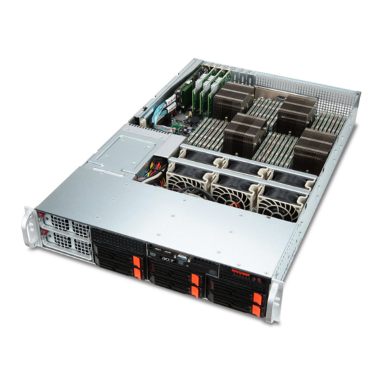
Page 15: External And Internal Structure
External and internal structure Front panel Icon Component Default power supply unit (PSU) Redundant PSU bay USB 2.0 ports Serial port Optical disc drive (ODD) Power failure LED indicator Icon Component Overheating/fan failure LED indicator LAN port 1/2 activity indicators HDD activity indicator Power indicator... - Page 16 Icon Component 3.5-inch hard disk drive (HDD) bays HDD access/failure LED indicator HDD rebuild/spare LED indicator Control panel LED indicator status Function Icon Power failure Overheating /fan failure LAN port 1/2 activity HDD activity Power state Icon Component HDD release button HDD security lock 2.5-inch hard disk drives...
- Page 17 Hot-plug HDD carrier LED indicator status Hard drive status Hard drive access Hard drive failure Hard drive rebuilding HDD hot spare Green - Blinking Green - On for SAS HDD, Off for SATA HDD Green - Blinking Green - Blinking Red - On Red - Blinking Red - Blinking...
-
Page 18: Rear Panel
Rear panel Icon Component PS/2 mouse port PS/2 keyboard port Dedicated IPMI LAN port (10/100) USB 2.0 ports Serial port Video port (VGA) Gigabit LAN ports 1 System tour Icon Component Expansion slot covers AC power plug for the redundant PSU AC power plug for the default PSU Gigabit LAN port link... - Page 19 Rear panel LED indicator status Function IPMI LAN port link IPMI LAN port activity Gigabit LAN port activity Gigabit LAN port link Status Indicated behavior Green 100 Mbps network link 10 Mbps network link Amber - Blinking Active connection Yellow - On Active connection Yellow - Blinking Transmit/receive activity...
-
Page 20: Internal Components
Internal components Component HDD backplane board Default PSU Mainboard Air shroud System fans 1 System tour... -
Page 21: Mainboard Layout
Mainboard layout Code PCI-E slot1 PCI-E slot2 PCI-E slot3 PCI-E slot4 CPU1 FAN9 LAN2 Component IPMI heartbeat LED PCIe Gen 2 x8 expansion slot PCIe Gen 2 x16 expansion slot PCIe Gen 2 x8 expansion slot PCIe Gen 2 x16 expansion slot Processor 1 socket Unit identifier button Processor 1 fan... - Page 22 Code LAN1 FAN8 P1 DIMM COM1 IPMI/LAN/USB0/USB1 Keyboard/Mouse CPU3 FAN7 P3 DIMM FAN1 CPU4 P4 DIMM FAN2 FAN3 FAN4 CPU2 P2 DIMM FAN5 FAN6 JPW1 JPW4 Component Gigabit Ethernet port 1 Chassis fan 8 Video port DDR3 DIMM slots for processor 1 Serial port 1 Dedicated IPMI LAN port/rear USB ports PS/2 keyboard and mouse ports...
- Page 23 Code JPW2 JPW3 JOH1 JPI2C1 T-SGPIO1 T-SGPIO2 SATA0-SATA5 USB4/5 header USB2/3 header USB6 JTPM1 JBT1 Battery COM2 JBT1 UIO slot JPB1 JPG1 JWD1 JSMB1 JPL1 Component +12V 8-pin power connector +12V 8-pin power connector Overheating warning header Power I C header Mainboard power-on LED Serial general purpose I/O header for SATA...
-
Page 24: Mainboard Jumper Settings
Mainboard jumper settings Code Function JPL1 Enable Gigabit LAN ports JWD1 Enable watchdog JPG1 Enable VGA port JPB1 Enable BMC JBT1 Clear CMOS 1 System tour Setting 1-2 Close: Enabled (default setting) 2-3 Close: Disabled 1-2 Close: Reset (default setting) 2-3 Close: NMI Open: Disabled 1-2 Close: Enabled (default setting) - Page 25 Mainboard LED Code Function IPMI heartbeat Mainboard power Status Description Flashing green BMC normal Green Power on...
- Page 26 1 System tour...
-
Page 27: Appendix A Server Management Tools
Appendix A Server management tools... -
Page 28: Server Management Overview
BMC, and configure RAID for the system hard drives. For detailed instructions on this utility, please refer to the Acer Smart Setup Help file. Acer Smart Console Remotely manage the server via a UPnP tool or a Web browser. -
Page 29: Adaptec Onboard Sata Raid Creation
RAID configuration utilities Adaptec Onboard SATA RAID Creation Configuring Adaptec onboard SATA RAID This section briefly shows how to create RAID volume with Adaptec onboard SATA RAID. Enabling onboard SATA RAID Turn on the server and the display monitor. If the server is already turned on, please close all open applications and then restart the server. - Page 30 Creating a RAID Volume Select Array Configuration Utility option. Select Create Array. The Select drives to create Array displayed. Select desired hard drive disk and then press <Insert> to add it in the Selected Drives area. Press <Enter> to complete the selection. Select Array Type.
-
Page 31: Megaraid 9260-8I Sas Raid Creation
MegaRAID 9260-8I SAS RAID Creation Configuring MegaRAID SAS 260-8I This section briefly shows how to create RAID volume with MegaRAID SAS 260-8I. Entering RAID BIOS Utility To enter the RAID BIOS Utility for MegaRAID SAS 260-8I, press <Ctrl> + <H> when you see the RAID BIOS prompt during POST. After POST finished, the Adapter Selection page will show on the screen. - Page 32 Initialing a RAID volume After creating the logical volumes on all of the RAID volumes, click Accept then Yes to save the configuration. Click Yes to initialize the new logical drives. You will see all the logical drives listed. Click Home to go back to the Configuration menu. Assigning a Hot Spare Drive Select a free disk marked as UNCONF GOOD and listed under Physical Drives.
-
Page 33: Appendix B Acer Smart Console
Appendix B Acer Smart Console... -
Page 34: Using Acer Smart Console
Using Acer Smart Console Acer Smart Console has a user-friendly graphical user interface (GUI) and a standard Internet browser. This article will help you become familiar with the Acer Smart Console. Each function will be described clearly. Acer Smart Console offers:... -
Page 35: Accessing Acer Smart Console
Username: root • Password: superuser Click Login. The Acer Smart Console page appears. Note: The default username is root and the default password is superuser. Both the username and password are case sensitive and should be entered in lower case each time. -
Page 36: Acer Smart Console User Interface
Acer Smart Console user interface The Acer Smart Console page opens once you have logged in. This page provides a central location for managing all connected servers. The user interface includes a system status alert indicator, function list, menu bar, function title, section information. -
Page 37: Server Health
Server Health Displays data related to the server's health, such as sensor readings and the event log. This menu has two options: Sensor Readings and Event Log. Sensor Readings Allows you to monitor status of the voltages of the power supply, the fan speed, processor and system temperature sensors. - Page 38 Appendix B Acer Smart Console Threshold Click Show Thresholds to view the threshold parameters of each sensor. It displays the Low Non-Critical (NC), High Non-Critical (NC), High Critical Threshold (CT) threshold information, and these items can not be modified. When each threshold matches alert level, system will send the alert to the specified destinations.
-
Page 39: Event Log
Event Log Provides a record of system events related to critical hardware components. It logs the events when the sensor triggers an abnormal state or is recovering from an abnormal state. When the log matches a pre-defined alert, the system will send out a notification automatically if pre-configured. -
Page 40: Configuration
The Configuration menu has the following options: • Alerts • Date and Time • LDAP • RADIUS • Mouse mode • Network • Dynamic DNS • Remote Session • SMTP • SSL Certificate • Users Appendix B Acer Smart Console... - Page 41 Alerts Allows you to designate up to 15 email recipients for notification of system alerts. When alerts occur, the system will send an email or a SNMP (Simple Network Management Protocol) trap containing the event detail to the designated recipients. The Alerts page allows you to do the following: •...
-
Page 42: Date And Time
Specify the event severity, such as Critical or Warning. Enter the recipient's email address. Enter a subject and message. Click Save. Date and Time The Date and Time option allows you to set the BMC date and time. Appendix B Acer Smart Console... - Page 43 LDAP (if available) The LDAP option allows you to download the user account list and authentication from the LDAP server and create Acer Smart Console user accounts from this list. Configuring LDAP settings On the LDAP Settings page and check Enable LDAP Authentication.
-
Page 44: Configuring Radius
RADIUS The RADIUS option allows you to configure the RADIUS option. Configuring RADIUS On the RADIUS Settings page check Enable RADIUS. Enter the required information to access the RADIUS server. Click Save. Appendix B Acer Smart Console... -
Page 45: Mouse Mode
Mouse mode The Mouse mode option allows you to set a mouse mode to control your mouse. Setting the mouse mode Select a mouse mode from the Mouse Mode page. • Absolute: Select this setting when using a Microsoft Windows operating system. -
Page 46: Configuring Network Settings
You can configure the network settings by using DHCP (Dynamic Host Configuration Protocol) or manually. Configuring network settings On the Network Settings page, select whether to obtain an IP address automatically or configure the network settings manually. Click Save. Appendix B Acer Smart Console... -
Page 47: Dynamic Dns
Dynamic DNS The Dynamic DNS option allows you to configure and change the management network parameters. Configuring Dynamic DNS On the Dynamic DNS Settings page, check Enable Dynamic DNS. Enter the required information to access the Dynamic DNS server. Click Save. -
Page 48: Remote Session
KVM or Media data during a redirection session. Select the remote session then press Save. Configuring Remote Session settings On the Remote Session page, select whether to enable KVM or Media Encryption. Select a Virtual Media Attach Mode. Click Save. Appendix B Acer Smart Console... - Page 49 SMTP The SMTP option allows you to configure the SMTP (Simple Mail Transfer Protocol) mail server settings. Configuring the SMTP settings On the SMTP Setting page, select a LAN channel number. Enter the IP address of the SMTP server. Enter the username and password. Enter the email address for sending email notifications.
- Page 50 SSL Upload The SSL Certificate option allows you to upload a SSL certificate manually. Uploading an SSL certificate On the SSL Upload page, click Browse to locate the SSL certificate on your system. Click Upload. Appendix B Acer Smart Console...
- Page 51 Users The Users option allows you to create, edit, delete, and view user accounts from the user list. To configure user accounts in the User List page, you can select from the following command buttons: • Delete User: Remove the user from the list. •...
-
Page 52: User Privileges
Modifying a user account On the Users page click Modify User. Enter the username. Enter the password. Re-enter the password. Select a privilege level from the drop-down menu. Click Modify. Appendix B Acer Smart Console... -
Page 53: Remote Control
Remote Control The Remote Control menu allows you to start a Remote Console session with the host system and manage power remotely. This menu include two options: KVM Remote Console Redirection and Server Power Control. KVM Remote Console Redirection The KVM Remote Console Redirection option allows you to start the KVM Remote Console utility and remotely manage the server using the monitor, mouse and keyboard as if you are connected directly to the server. -
Page 54: Server Power Control
Appendix B Acer Smart Console Server Power Control The Server Power Control option allows you to perform a remote power on, power off, power cycle and reset your server. Performing a remote power control operation On the Server Power Control page, select an option then click Perform... -
Page 55: Launch Sol
Launch SOL SOL allows you to launch the remote console by using Serial over LAN. Click Launch SOL. Select the Baud rate from the pull-down menu as your SOL transfer rate. Make sure that the Baud rate selected here matches the Baud Rate set in the BIOS. Once you have selected the Baud rate, and press Start to start the session. -
Page 56: Virtual Media
Appendix B Acer Smart Console Virtual Media Floppy disk This floppy disk option allows you to upload and share images via the BMC. These images will then be emulated to the host server as USB applications. Perform the floppy disk operation On the floppy disk page select an image file, then click Upload to upload your image file to the server. -
Page 57: Cd-Rom Image
CD-ROM image This option allows you to upload and share images via the BMC. These images will then be emulated to the host server as USB applications. Perform the CD-ROM operation On the CD-ROM Setting page, enter the share host server. Enter the path to the CD-ROM image file. -
Page 58: Maintenance
Maintenance Firmware Update Maintenance allows you to upgrade the BMC firmware (including Acer Smart Console and FRU information). Upgrading firmware On the Maintenance page click Enter Update Mode. The Firmware Upload page appears. Click Browse to locate the firmware image file. -
Page 59: Kvm Function Description
Snooping code for BIOS LPC Port80. KVM function description You can launch the KVM Remote Console utility from the Acer Smart Console Remote Control menu. The KVM Remote Console utility enables you to control any programs on the server remotely, using a local keyboard, monitor and mouse. -
Page 60: Virtual Keyboard
<Left Alt> key. • Right Windows Key: This item performs the same function as pressing the <Right Windows> key. Right click this item to select Hold Down or Press & Release for the <Right Windows> key function. Appendix B Acer Smart Console... - Page 61 • Left Windows Key: This item performs the same function as pressing the <Left Windows> key. Right click this item to select Press Down or Press & Release for the <Left Windows> key function. • Macro: Click this item to activate a pull-down submenu displaying Macro hotkeys.
- Page 62 Once keyboard support is enabled, you can configure repeat key timeout settings. Repeat Key Timeout: Use the handle on the slider to select the appropriate timeout settings for repeat keystrokes from 0 ms (millisecond) to 1000 ms (millisecond). Appendix B Acer Smart Console...
-
Page 63: Full Screen Mode
Language From the Preferences submenu, select Language settings. From the language settings pop-up menu select the language you want to use for console redirection. The language options are: English, Japanese, German, French, Spanish, Korean, and Italian. Once you have selected a language to use, click OK. Window From the Preference submenu, click Window to display the submenu. -
Page 64: User List
This feature allows you to access the user list. Session ID: This item displays the current session ID#. User Name: This item displays the name(s) of the user(s). IP Address: This item displays the IP Address of the host server. Appendix B Acer Smart Console... -
Page 65: Exit
Capture This feature allows you to capture the screen display on your remote console. Full Screen Capture: Click this item to capture the full screen video display. Exit Yes: At the prompt, click Yes to exit from remote redirection. No: Click No to return to the current session. - Page 66 Appendix B Acer Smart Console...
-
Page 67: Index
Index front panel hard disk drive activity indicator, location location RAID configuration HDD, see hard disk drive internal components LAN port activity LED indicator location LED indicators control panel HDD carrier IPMI LAN port activity/link LAN port activity LAN port activity/link mainboard overheating/fan failure PSU failure...
Need help?
Do you have a question about the AR585 F1 and is the answer not in the manual?
Questions and answers