Table of Contents
Advertisement
Available languages
Available languages
Quick Links
INSTALLATION MANUAL
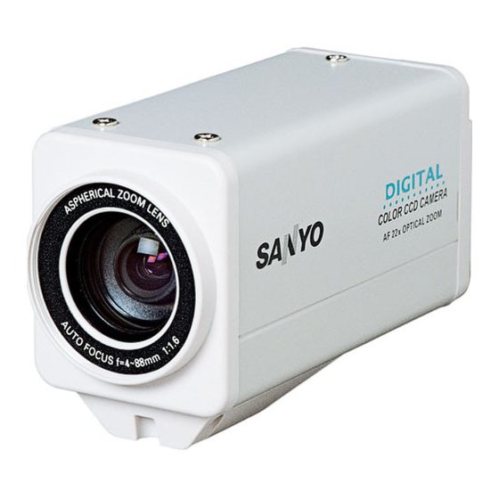
Color CCD Camera
THIS INSTALLATION SHOULD BE MADE BY A QUALIFIED
SERVICE PERSON AND SHOULD CONFORM TO ALL LOCAL
CODES.
Please read this installation manual carefully in order to ensure correct installation. In addition,
be sure to read carefully the electronic manual contained in the CD-ROM to ensure correct
operation of the camera.
● Installation accessory
Clamping core
Installing Camera
Changing the Bracket for Mounting the
Camera
• Make sure to use the longer screws (A) to
secure the bracket.
(B)
Lens cap
(A)
✱ Hole for mounting the camera (Remove the screw before mounting the camera.)
Contents
Information To User. . . . . . . . . . . . . . . . . . . . 1
Parts Names and Functions . . . . . . . . . . . . . 3
Connections. . . . . . . . . . . . . . . . . . . . . . . . . . 5
Features . . . . . . . . . . . . . . . . . . . . . . . . . . . . . 7
How to Perform the Settings in the Menu
Screens . . . . . . . . . . . . . . . . . . . . . . . . . . . . . 9
Learning the Menu Setting Operations . . . 10
Main specifications . . . . . . . . . . . . . . . . . . . 13
Dimensions . . . . . . . . . . . . . . . . . . Back page
Install the camera in a correct location so
that the intended object can be monitored
properly.
You should also adjust on the monitor
side.
(A)
• If you want to use a commercially available
platform for the camera, select an
appropriate type, taking into consideration
the gross weight of the camera and
platform, and secure it on a firm place.
✱
• Images may blur under extremely bright
lighting; adjust the lighting angle to get
clear images.
(B)
VCC-ZM600
Advertisement
Chapters
Table of Contents

Related Manuals for Sanyo VCC-ZM600


Summary of Contents for Sanyo VCC-ZM600
-
Page 1: Table Of Contents
INSTALLATION MANUAL Color CCD Camera THIS INSTALLATION SHOULD BE MADE BY A QUALIFIED VCC-ZM600 SERVICE PERSON AND SHOULD CONFORM TO ALL LOCAL CODES. Please read this installation manual carefully in order to ensure correct installation. In addition, be sure to read carefully the electronic manual contained in the CD-ROM to ensure correct operation of the camera. -
Page 2: Information To User
If water or liquid gets inside the unit, turn off the power immediately and disconnect the power cord, and then consult your dealer or an Authorized Sanyo Service Center. ■ Be careful when handling the unit To prevent damage, do not drop the unit or subject it to strong shock or vibration. - Page 3 This class B digital apparatus complies with Canadian ICES-003. This installation manual and the electronic manual are copyrighted by SANYO Electric Co., Ltd. No materials contained in these manuals may be reproduced in any format without the prior permission of the copyright holder.
-
Page 4: Parts Names And Functions
Parts Names and Functions Rear panel VIDEO OUT connector (BNC type) Outputs video signal. Connect this terminal to the video input terminal of the external device. Control terminals (Push-lock) Used to perform the control functions such as controlling the camera remotely or inputting/ RS485 outputting alarm. -
Page 5: Side Panel
Side panel System terminals (Push-lock) Used to connect external system control devices. RS-485 control terminals (Push-lock) Used to perform remote operations of the camera. Connect these terminals to a communication device such as system controller. COM terminal (earth terminal) UTP terminals b For zoom/focus Used to output video signal using a UTP While viewing the live image, you can perform... -
Page 6: Connections
Do not connect the power cord until all other Connections connections have been completed. ✱1 Alarm Signal Input For details, see “Setting the Alarm Input (ALARM IN)” in the electronic manual contained in the CD-ROM. POWER VIDEO OUT SYNC CAMERA RS485 LENS ALARM... -
Page 7: Monitor Connection
Connection with a communication device for remote operation Controller ✱3 UTP (Unshield Twist Pair) cable: LAN Category 5 or higher ✱3 SYSTEM DEVICE (ex. Monitor) Receiver Digital Video To output video signal, Recorder etc. select the connection of a coaxial cable or a UTP cable. -
Page 8: Features
& You can perform the settings on the camera by Features navigating through the menu screens. Zooming Function Alarm Settings b The camera has a built-in motion sensor. b You can store the zoom and focus & [CAMERA] ⇒ [MOTION] ⇒ [ON] settings of surveillance locations by camera setting number. -
Page 9: Privacy Masks
Day/Night Function White Balance Adjustment According to the luminance level, the In addition to the white balance viewing mode will be switched adjustment, you can use the mask automatically between the color mode patterns to cover extremely bright or and the black/white mode. dark light source in the monitored image so that the white balance adjustment is You can adjust the luminance threshold... -
Page 10: Screens
How to Perform the Settings in the Menu Screens A Using the buttons on the This manual and the electronic manual which is contained in the supplied camera CD-ROM describe the operations using the buttons on the camera. The optional camera control unit (VAC-70) can be used to perform same operations as the camera. -
Page 11: Learning The Menu Setting Operations
Learning the Menu Setting Operations Display the main menu. Select a setting value. Setting value SYNC CAMERA LENS Press and hold the button for ALARM about 3 seconds. PRIVACY MASK PASSWORD LANGUAGE OPTION <Main menu> SYNC CAMERA LENS ALARM PRIVACY MASK PASSWORD LANGUAGE OPTION... - Page 12 Learning the Menu Setting Operations Return to the previous screen. Exit from the menu screen. Select [MENU] – “BACK” at the bottom of the Select [MENU] – “BACK” at the bottom of the screen, use the dc button to select “END”, screen, and press the SET button.
-
Page 13: Using The Electronic Manual (Cd-Rom)
Using the Electronic Manual (CD-ROM) The menu screens enable you to easily perform setting and adjustment of this camera. By using the electronic manual which is contained in the supplied CD-ROM, you can access extensive information from basic operation to advanced settings and functions, as well as troubleshooting. -
Page 14: Main Specifications
Main specifications Television system NTSC color standards Image sensor 1/4" interline transfer CCD Effective pixels 768 (Horizontal) x 494 (Vertical) Scanning system 2:1 interlaced, 525 lines Synchronization method Internal synchronization/Line lock (with vertical phase adjustment) Video output 1.0 V (p-p)/75Ω, BNC connector Horizontal resolution 540 TV lines, typical Lowest image illumination... - Page 15 MANUEL D’INSTALLATION Caméra CCD couleurs CETTE INSTALLATION DOIT ETRE EFFECTUEE PAR UNE VCC-ZM600 PERSONNE QUALIFIEE DU SERVICE TECHNIQUE ET DOIT ETRE CONFORME A TOUS LES CODES LOCAUX. Veuillez lire ce manuel d’installation très attentivement afin d’effectuer une installation correcte. Veuillez également lire très attentivement le manuel électronique contenu dans le CD-ROM afin de faire fonctionner la caméra correctement.
-
Page 16: Informations Pour L'utilisateur
Faites attention lors de l’installation près du d’alimentation, puis adressez-vous à votre plafond, dans une cuisine ou dans une chambre revendeur ou à un Centre de service Sanyo des machines, car la température risque de autorisé. monter à un niveau élevé. - Page 17 Cet appareil numérique de classe B est conforme à la norme canadienne ICES-003. This installation manual and the electronic manual are copyrighted by SANYO Electric Co., Ltd. No materials contained in these manuals may be reproduced in any format without the prior...
-
Page 18: Dénomination Et Fonctions Des Pièces
Dénomination et fonctions des pièces Panneau arrière Connecteur VIDEO OUT (type BNC) Émet signal vidéo. Connectez cette connecteur à la borne d’entrée vidéo de l’appareil externe. Bornes de commande à poussoir Pour les fonctions de commande comme la commande à distance de la caméra ou la RS485 entrée/sortie d’alarmes. - Page 19 Panneau latéral Bornes de système (Verrouillage à poussoir) Sert à connecter des appareils externes de contrôle système. Bornes de commande RS-485 à poussoir Utilisé pour le fonctionnement à distance de la caméra. Reliez ces bornes à un appareil de communication (contrôleur de système par ex.).
-
Page 20: Branchements
Ne branchez pas le cordon d’alimentation tant que Branchements les autres branchements n’ont pas ete effectues. ✱1 Entrée du signal d’alarme Pour tout détail, consultez « Réglage de l’entrée d’alarme (ENT ALARME) » dans le manuel électronique contenu dans le CD-ROM. POWER VIDEO OUT SYNC... - Page 21 Connexion avec un appareil de communication pour la commande à distance Contrôleur ✱3 Câble UTP (Unshield Twist Pair - paire torsadée non blindée): LAN de catégorie 5 ou supérieure ✱3 SYSTEM DEVICES (ex. Moniteur) Récepteur Enregistreur vidéo Pour émettre un signal numérique, etc.
-
Page 22: Caractéristiques
& Vous pouvez effectuer les différents réglages sur la Caractéristiques caméra en naviguant à travers les écrans de menu. Fonction zoom Réglages alarme b La caméra est équipée d’un détecteur de b Vous pouvez mémoriser les réglages de zoom et de mise au point des positions mouvement intégré. - Page 23 Fonction Jour/Nuit Réglage de l’équilibrage des blancs Selon le niveau de luminance, le mode de En plus de l’équilibrage des blancs, vous visualisation commute automatiquement pouvez utiliser les masques pour couvrir entre le mode couleur et le mode noir et toute source intense d’ombre ou de lumière blanc.
- Page 24 Comment effectuer les réglages dans les écrans de menu A Avec les boutons de la caméra Ce manuel et le manuel électronique, contenu dans le CD-ROM fourni, décrivent les opérations réalisables avec les boutons de la caméra. La télécommande en option (VAC-70) peut effectuer les mêmes opérations que la caméra.
-
Page 25: Apprentissage Des Opérations De Réglage
Apprentissage des opérations de réglage menu Sélectionnez une valeur de Affichez le menu principal. réglage. Valeur de réglage SYNC Appuyez et maintenez enfoncé le CAMERA LENTILLE bouton pendant environ 3 secondes. ALARME MASQUE M/PASSE <Menu principal> LANGUE OPTION SYNC CAMERA LENTILLE ALARME MASQUE... - Page 26 Apprentissage des opérations de réglage menu Retournez à l’écran précédent. Sortez de l’écran de menu Sélectionnez [MENU] – « RETOUR » au bas Sélectionnez [MENU] – « RETOUR » au bas de l’écran ; utilisez le bouton dc pour de l’écran, puis pressez le bouton SET. sélectionner «...
-
Page 27: Utilisation Du Manuel Électronique
Utilisation du manuel électronique (CD-ROM) Les écrans de menu vous permettent de régler et d’ajuster la caméra de façon simple. Le manuel électronique, contenu dans le CD-ROM fourni, vous permet d’accéder à des informations approfondies allant du fonctionnement de base aux fonctions et réglages avancés et à... -
Page 28: Spécifications Principales
Spécifications principales Système de télévision Standards couleur NTSC Capteur d’images CCD transfert interligne 1/4" Pixels effectifs 768 (Horiz. x 494 (Vert.) Système de balayage 2:1 entrelacé, 525 lignes Mode de synchronisation Synchronisation interne/Line lock (avec ajustement de la phase verticale) Sortie vidéo 1,0 V (p-p)/75Ω, connecteur BNC Résolution horizontale... -
Page 29: Dimensions
MANUAL DE INSTALACIÓN Cámara CCD a color LA INSTALACIÓN TIENE QUE SER REALIZADA POR UNA VCC-ZM600 PERSONA DE SERVICIO Y TIENE QUE ESTAR DE ACUERDO CON LOS CÓDIGOS LOCALES. Leer atentamente este manual de instalación para garantizar que se realiza una instalación correcta. -
Page 30: Información Para El Usuario
• No use bencina, disolvente ni ningún otro centro de servicio autorizado Sanyo. producto químico para limpiar el exterior, pues pueden causar deformaciones y despintar el ■ No la abra ni la modifique exterior. - Page 31 Este aparato digital de la clase B cumple con el ICES-003 canadiense. Este manual de instalación y el manual electrónico están sujetos a derechos de autor de SANYO Electric Co., Ltd. Los materiales contenidos en estos manuales no pueden reproducirse con ningún medio sin la...
-
Page 32: Nombres Y Funciones De La Piezas
Nombres y funciones de la piezas Panel trasero 1 Conector VIDEO OUT (tipo BNC) Produce señales de vídeo. Conectar este conector al terminal de entrada de vídeo del dispositivo externo. 2 Terminales de control (bloqueo por empuje) RS485 Se usa para realizar las funciones de control como el control de la cámara a distancia o la entrada/salida de alarmas. - Page 33 Panel lateral 3 Terminales de sistema (bloqueo por empuje) Se usan para conectar los dispositivos de control del sistema externo. 1 Terminales de control RS-485 (bloqueo por empuje) Se usan para realizar operaciones a distancia de la cámara. Conectar estos terminales a un dispositivo de comunicación como un controlador de sistema.
-
Page 34: Conexiones
No conectar el cable de alimentación hasta que no Conexiones se haya terminado con todas las conexiones. ✱1 Entrada de señal de alarma Para mayor información, consultar “Ajuste de la entrada de alarmas (ENTRADA ALARMA)” en el manual electrónico contenido en el CD-ROM. POWER VIDEO OUT SINC... - Page 35 Conexión con un dispositivo de comunicación para el funcionamiento a distancia Controlador ✱3 Cable UTP (Unshield Twist Pair, o par trenzado sin blindaje): categoría LAN 5 o superior ✱3 SYSTEM DEVICES (ej. Monitor) Receptor Grabador de vídeo digital, etc. Para producir la señal de vídeo, seleccionar la conexión de un cable coaxial o un cable UTP.
-
Page 36: Características
& Es posible realizar los ajustes en la cámara Características navegando a través de las pantallas del menú. Función de zoom Ajustes de alarma b La cámara está provista de un sensor de b Es posible almacenar los ajustes de zoom y enfoque de lugares de vigilancia movimiento incorporado. - Page 37 Función Día/Noche Ajuste de balance de blanco En función del nivel de luminancia, el modo Además del ajuste de balance de blanco, es de visualización se cambia posible usar patrones de máscara para automáticamente entre el modo color y el cubrir fuentes de luz muy brillantes u modo blanco y negro.
-
Page 38: Realización De Los Ajustes En Las Pantallas
Realización de los ajustes en las pantallas del menú A Usando los botones de la Este manual y el manual electrónico contenido en el CD-ROM suministrado cámara describen las operaciones que se pueden realizar con los botones de la cámara. La unidad de control de la cámara opcional (VAC-70) puede usarse para realizar las mismas operaciones que la cámara. - Page 39 Aprendizaje de las operaciones de ajuste del menú Visualización del menú Selección de un valor de ajuste. principal. Valor de ajuste SINC CAMARA LENTE ALARMA Pulsar y mantener pulsado el MASCARA PRIV botón durante unos 3 segundos. CONTRASENA IDIOMA OPCION <Menú...
- Page 40 Aprendizaje de las operaciones de ajuste del menú Volver a la pantalla anterior. Salir de la pantalla del menú Seleccionar [MENU] – “ATRAS” en la parte Seleccionar [MENU] – “ATRAS” en la parte inferior de la pantalla, usar el botón dc inferior de la pantalla, y pulsar el botón SET.
-
Page 41: Uso Del Manual Electrónico (Cd-Rom)
Uso del Manual Electrónico (CD-ROM) Las pantallas del menú permiten configurar y ajustar la cámara con facilidad. Usando el manual electrónico contenido en el CD-ROM suministrado con la cámara, se puede acceder a información exhaustiva que va desde el funcionamiento básico hasta los ajustes y funciones avanzadas, e incluye la localización y solución de anomalías. -
Page 42: Especificaciones Principales
Especificaciones principales Sistemas de televisión NTSC estándar color Sensor de imágenes CCD transferencia interlínea 1/4" Píxeles efectivos 768 (Horizontal) x 494 (Vertical) Sistema de exploración 2:1 entrelazado, 525 líneas Método de sincronización Sincronización interna/Bloqueo línea (con ajuste de la fase vertical) Salida de vídeo 1,0 V (p-p)/75Ω, conector BNC Resolución horizontal... - Page 43 MEMO ................. .
- Page 44 Dimensions 56 (2.2) (0.1) 147 (5.8) 10 (0.4) Unit: mm (inch) 1/4"-20UNC SANYO Electric Co., Ltd. 1AC6P1P3257-- L5CB2/US (1107KP-HS) Printed in China...
Need help?
Do you have a question about the VCC-ZM600 and is the answer not in the manual?
Questions and answers