Table of Contents
Advertisement
Advertisement
Table of Contents

Related Manuals for Bosch LTC 5136/61


Summary of Contents for Bosch LTC 5136/61
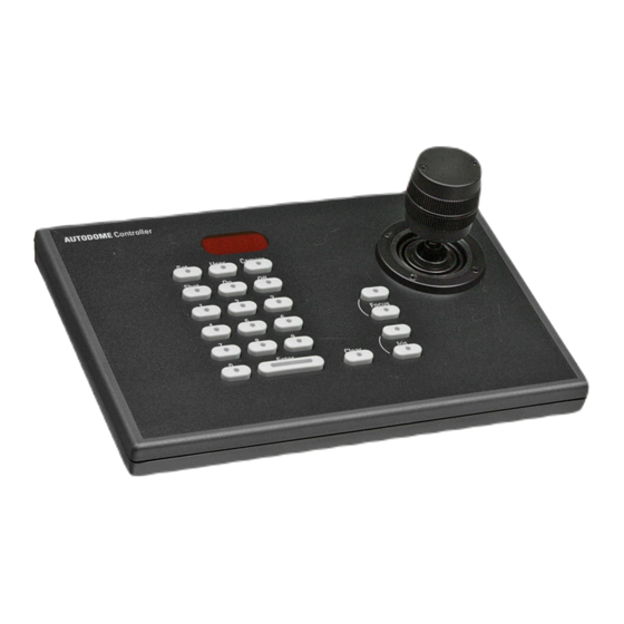
- Page 1 LTC 5136 Series Instruction Manual ® EN AutoDome Controller...
-
Page 2: Important Safeguards
If you are not sure of the type of power supply you plan to use, consult your dealer or local power company. For units intended to operate from battery power or other sources, refer to the operating instructions. Bosch Security Systems | 04 September 2003... - Page 3 Government Printing Office, Washington, DC 20402, wall outlet and disconnect the cable system. This Stock No. 004-000-00345-4. will prevent damage to the unit due to lightning and power line surges. Bosch Security Systems | 04 September 2003...
-
Page 4: Safety Precautions
ON-OFF switch is in the ON est sur la position ON (marche). Le cordon position. The power cord is the main power d’alimentation est l’organe de coupure principal disconnect for all units. de l’alimentation pour tous les appareils. Bosch Security Systems | 04 September 2003... - Page 5 Geräten erfolgt das Abtrennen der igual forma, pero adicionalmente requieren que Spannungsversorgung über das Netzkabel. el interruptor esté posicionado en ON. El cable de alimentación es el medio principal de desconexión del equipo. Bosch Security Systems | 04 September 2003...
- Page 6 ON. Il cavo di alimentazione serve a bedrijfsklaar als de AAN/UIT-schakelaar in de scollegare dalla corrente tutti gli apparecchi. AAN-stand staat. Losnemen van het netsnoer is voor alle units de belangrijkste manier om de spanning te onderbreken. Bosch Security Systems | 04 September 2003...
- Page 7 ON-OFF se encontrar na posição ON. Para desligar a electricidade em qualquer uma das unidades deve ser utilizado o cabo eléctrico. Bosch Security Systems | 04 September 2003...
-
Page 8: Table Of Contents
DATA CONVERTER PINOUTS ..........19 Bosch Security Systems | 04 September 2003... -
Page 9: Unpacking
The biphase control code cable can extend a replace it properly in its carton and notify the shipper. maximum distance of 1.5 km (5000 ft), using If any items are missing, notify your Bosch Security 1.0 mm (18 AWG) shielded twisted pair cable Systems, Inc. -
Page 10: Installation
This document also includes various diagrams of typical applications, that will be helpful to refer to during installation. Bosch Security Systems | 04 September 2003... -
Page 11: Installation Using Rs-232 Data Direct To Camera Site
If the power to complete the installation. supply cable must be attached to the power supply, the polarity is not important; the Interface Unit is not Bosch Security Systems | 04 September 2003... -
Page 12: Installation Using An Rs-232 Data Transmission Link To A Biphase Camera Site
NOTE: The shield terminals of the interface unit are RS-232 TX output, and Pin 4 is the Signal Ground connected to the Shield wire of the cable. connection. Be sure to use cable suitable for RS-232 Bosch Security Systems | 04 September 2003... -
Page 13: Autodome Camera Or Receiver/Driver Site Configuration
If the camera’s Fast Address is the same as the keyboard address, ON-999-ENTER will make the camera enter the Fast Address mode. This is required to change or disable a Fast Address. Figure FA3 Bosch Security Systems | 04 September 2003... -
Page 14: Controller Operation
Certain pre-position numbers are also used to program certain AutoDome features. Refer to the AutoDome operation manual for a complete listing of the available features. USER key: Press USER-1-ENTER to enter the Controller diagnostic mode. This function can be used Bosch Security Systems | 04 September 2003... - Page 15 ENTER to complete the action. Certain auxiliary numbers are also used to program certain AutoDome features. Refer to the AutoDome operation manual for a complete listing of the available features. Bosch Security Systems | 04 September 2003...
-
Page 16: Technical Reference
Switcher Unit Typical biphase control code output RS-232 Data & Power Typical AutoDome Cameras or Controller Allegiant Receiver/Driver units Figure 4 Typical Multiple Camera Sites Using Daisy Chain Biphase Control Code Wiring Configuration Bosch Security Systems | 04 September 2003... - Page 17 RS-232 Cable or LTC 8557 Communication Link Junction Box Typical AutoDome Controller Cameras or Allegiant RS-232 Data & Power Receiver/Driver units Figure 6 Typical Installation Using RS-232 Communication Link to Biphase Camera Site Bosch Security Systems | 04 September 2003...
- Page 18 3. Rx (Not used) 4. Tx 5. Signal Ground 6. 12V Pin 6 Pin 1 Figure 8 Rear Panel Controller Connector Detail 6.08 4.80 4.26 2.75 Figure 9 Mounting Dimensions of Supplied Interface Box Bosch Security Systems | 04 September 2003...
-
Page 19: Data Converter Pinouts
Data In - 9-Pin Connector (Male) Connection No Connection No Connection No Connection Ground No Connection No Connection No Connection No Connection KBD - RJ-11 Designations (If Used) Connection Output Voltage Signal Ground Ground No Connection Output Voltage Bosch Security Systems | 04 September 2003... - Page 20 Tel: 800-326-3270 70049 Stuttgart The Netherlands Fax: 1-717-735-6560 Telefax (0711) 8 11-12 34 Tele +31 40 27 80000 www.boschsecuritysystems.com © 2003 Bosch Security Systems GmbH 3935 890 06114 03-37 | September 11, 2003 | Data subject to change without notice.
Need help?
Do you have a question about the LTC 5136/61 and is the answer not in the manual?
Questions and answers