
Related Manuals for LEHNER Polaro XL


Summary of Contents for LEHNER Polaro XL
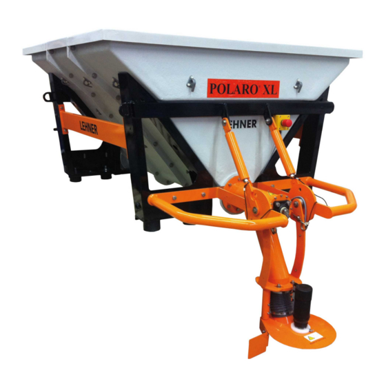
- Page 1 LEHNER ® POLARO L/XL Operating manual with spare parts list Last updated: October 2011 Serial number: ..............Translation of the original version...
- Page 3 LEHNER Maschinenbau GmbH Haeuslesaecker 14 D-89198 Westerstetten, Germany Tel.: +49 7348 9596-22 Fax: +49 7348 9596-40 www.lehner.eu info@lehner.eu This document must not be distributed, duplicated or utilised, nor may its content be communicated without express permission. Compensation will be sought for all breaches. All rights reserved in the event of patent, utility model or design registration.
-
Page 4: Table Of Contents
Table of contents Index What you should know ............6 Foreword ....................6 About this operating manual..............6 Description of the POLARO L/XL ..............7 ® Intended use .................... 9 Reasonably predictable misuse .............. 9 Warranty ....................9 About your safety .................. 10 Emergency Stop switch ................. - Page 5 Table of contents Set the spreading zone ................. 28 Empty sensor ..................29 Settings and displays ............31 Make settings ..................31 Spreader settings .................. 32 4.2.1 Reset day-hour counter ................. 32 4.2.2 Vibrator current threshold ..............32 4.2.3 Vibrator on duty cycle ................33 Service query ..................
-
Page 6: What You Should Know
1 What you should know 1.1 Foreword Congratulations on purchasing the POLARO L/XL, a high-quality ® and innovative product. Thank you for placing your trust in us. Thanks to its advanced design, meticulous material selection, state-of-the art manufacturing techniques and the precision work of our employees, this equipment meets all efficiency, quality, reliability and value requirements. -
Page 7: Description Of The Polaro ® L/Xl
1 What you should know Warnings Warnings in this operating manual are identified as follows: Danger! Warning against immediate danger. Non-observance of appropriate measures will result in death or severe personal injury. Warning! Warning of possible danger. Death or severe personal injury is possible. Caution! Warning of possible dangerous situations. Slight personal injury or damage to property is possible. - Page 8 1 What you should know Technical data POLARO POLARO ® ® Dimensions L/W/H 1037/1056/820 1394/1056/820 Net weight 140 kg 155 kg Capacity 380 l 550 l Salt capacity approx. 500 kg approx. 720 kg For 20 g/m² 25,000 m² 36,000 m² Spreading width [m] approx.
-
Page 9: Intended Use
1 What you should know 1.4 Intended use The POLARO L/XL is a spreader for spreading winter salt, gravel and ® sand. 1.5 Reasonably predictable misuse Use the device only on approved carrier vehicles with an adequate axle load. Use the device only for approved spreading materials The device must not be used for spreading crop protection products. -
Page 10: About Your Safety
• Spreading tables and additional information about the spreading material used can be requested from the spreading material manufacturer in question. • LEHNER Agrar GmbH cannot accept any liability for the storage and application of the spreading material. -
Page 11: Emergency Stop Switch
1 What you should know 1.8 Emergency Stop switch Warning! Danger of death from non-functional safety equipment! Your safety is only assured if all safety equipment is intact. Therefore: • Check before starting work that the safety equipment is functional and correctly installed. •... - Page 12 1 What you should know Warning! Danger of death by uncontrolled reactivation! Uncontrolled reactivation may cause serious injuries or death. Therefore: • Before switching on again ensure that the cause of the Emergency Stop has been rectified. • All safety equipment is installed and functional. •...
-
Page 13: Mounting And Starting
2 Mounting and starting 2.1 Install the frame Danger! Danger of death of very serious injuries caused by falling loads Lift the spreader only with adequately sized handling equipment and lifting gear Do not stand under suspended loads. When you place the spreader on the load space of the carrier vehicle, ensure that it is stable Caution! Damage to carrier vehicle... - Page 14 2 Mounting and starting 1. The spreader (1) is bolted to a special palette for transport. Undo four screws (3) on the frame. 2. Position the spreader (1) on the load space of the carrier vehicle using adequately sized handling equipment and lifting gear. The eight feet (4) of the frame must stand on the load space.
-
Page 15: Set The Working Height Of The Spreading Disk
2 Mounting and starting Packaging materials Dispose of packaging materials properly or save them to return to the manufacturer. Raised the special pallet, it is ideally designed for transporting the spreader. 2.2 Set the working height of the spreading disk Caution! Risk of equipment damage When raising and lowering the spreading device, the spreading... -
Page 16: Install The Cross Bar
2 Mounting and starting 5. Slide the disk mounting (4) downwards or upwards to adjust the discharge height, whilst monitoring the drive motor cable. 6. Resecure the cable if necessary. 7. Secure the disk mounting (4) with four screws (5). 2.3 Install the cross bar Caution! Risk of equipment damage... -
Page 17: Electrical Connection
2 Mounting and starting 2.4 Electrical connection Caution! Danger of short circuit Ensure that the cables are routed without tension, kinking and chafing, and also avoid routing them around sharp edges. Caution! Risk of equipment damage Faulty cables or cables with incorrect dimensions can lead to malfunctions and damage to the device. Only use original cables, or ones approved by the manufacturer. -
Page 18: Fill And Cover The Spreading Material Tank
2 Mounting and starting 4. Remove the transport cover (1) and connect the two sockets (3) and (4), ensuring that they are locked correctly (6). 5. Secure the battery cable and data cable to the carrier vehicle. The device is now ready for use. 2.5 Fill and cover the spreading material tank Warning! Risk of injury by falling tarpaulin... - Page 19 2 Mounting and starting 1. Check the tank (2) and clean it if necessary, there must be no foreign bodies, foil residue, packaging or similar items in the tank (2). 2. Fill the tank with spreading material immediately before starting work. Pour the spreading material slowly and evenly into the tank.
-
Page 20: Operating The Polaro ® L/Xl
3 Operating the POLARO L/XL ® 3.1 Controls on the control panel 1 Switching on / off 2 Esc key to go to the main menu 3 Plus and minus keys to change parameters 4 Enter key to confirm the selected menu or setting 5 Display 6 Change key to change between menus 7 Programme keys 1 - 4 8 Assignment keys, for example for rotating light and working light 9 Start/Stop for various programs or spreaders... -
Page 21: Indicators In The Display
3 Operating the POLARO L/XL ® 3.2 Indicators in the display Main menu 1 Arrow denotes the active line 2 Spreading disk position 3 Screw speed 4 Spreading disk speed Error message For more information, see chapter 6.5 - Troubleshooting. -
Page 22: Switch The Spreader On And Off
3 Operating the POLARO L/XL ® 3.3 Switch the spreader on and off Danger! Risk of injury by accident When travelling on public roads and tracks used by agricultural vehicles, follow the applicable rules of the road. Warning! Risk of injury Do not take the spreader into operation if there are technical safety defects. - Page 23 3 Operating the POLARO L/XL ® Screw drive automatic start/automatic clear If an excessive load makes it difficult for the screw drive to start, the controller will switch to "Breakaway mode". The screw will change direction several times. If the screw is unable to break away by this action, the drive motor will be shut down automatically. The following message is shown in the display: Spreader stopped Spreader blocked...
- Page 24 3 Operating the POLARO L/XL ® To eliminate the blockage: 1. Switch off the spreader. 2. Turn the hex screw (1) to the right and left using a 27 mm wrench to move the screw manually. 3. Take the wrench of the hex screw (1). 4.
-
Page 25: Calibration And Spreading Width
3 Operating the POLARO L/XL ® 3.5 Calibration and spreading width The spreading volume depends on the speed of the screw, it can be found through the calibration process. Turning Warning! Risk of crush injury by rotating screw Do not reach into the material discharge during the calibration. Ensure that nobody else can reach into the material discharge Caution! Risk of equipment damage... - Page 26 3 Operating the POLARO L/XL ® Press the key to start the calibration. Calibration 60 sec The calibration will stop automatically Screw 80 rpm after 60 seconds. 3. Weigh the discharged material. 4. Repeat the calibration if necessary until you find a suitable screw speed. Determining the spreading width 1. Spread on a firm surface. 2.
-
Page 27: Set The Speed Of The Screw/Spreading Disk
3 Operating the POLARO L/XL ® 3.6 Set the speed of the screw/spreading disk If necessary, press the button to select > Screw 80 rpm the screw or spreading disk; the arrow Disk ↑ 600 rpm points to the first line in the display. Press the key to set the screw speed. The speed can be set to any value. -
Page 28: Set The Spreading Zone
3 Operating the POLARO L/XL ® 3.8 Set the spreading zone You can set the zone within which the spreading material is to be spread. This allows you to spread the material on a pavement for example when the carrier vehicle is running along the road. Basic setting 1. -
Page 29: Empty Sensor
3 Operating the POLARO L/XL ® Final adjustment You can adjust the winnowing fans on the spreading disk to improve the spreading zone: 1. Undo both screws (2) until the winnowing fan (1) can be moved. 2. Adjust the winnowing fan (1): 3. - Page 30 3 Operating the POLARO L/XL ® 3.10 Residual discharge The tank should be emptied after use to prevent the material forming lumps or freezing, for example overnight due to humidity. Press the key to switch on the control > Screw 80 rpm panel.
-
Page 31: Settings And Displays
4 Settings and displays The control panel enables you to set the language and make the following control settings: • Reset day-hour counter • Vibrator current threshold • Vibrator on duty cycle In addition you can view the service query. 4.1 Make settings Switch off the machine. -
Page 32: Spreader Settings
4 Settings and displays 4.2 Spreader settings 4.2.1 Reset day-hour counter Press the key, the current value for the Day-hour counter day-hour counter will be displayed. 00 h 00 min Press the key again to reset the day- hour counter. Press the key to save the setting. -
Page 33: Vibrator On Duty Cycle
4 Settings and displays 4.2.3 Vibrator on duty cycle Press the key, the day-hour counter will Day-hour counter be displayed. 00 h 00 min Press the key twice, the vibrator on duty Vibrator on duty cycle cycle will be displayed. 13 sec Press the key to set the on duty cycle. -
Page 34: Service Query
4 Settings and displays 4.3 Service query Voltage and current check The spreader must be switched on to check the electrical voltage (in V) and current (in A). Press the key, the electrical voltage and Service-Screw current for the screw will be displayed. 16. - Page 35 4 Settings and displays Display the spreader version Press the key, the electrical voltage and current for the screw will be displayed. Press the key five times, the spreader Spreader version version will be displayed. HW: xx.xx SW: xx.xx Press the key to return to the main menu.
-
Page 36: Language
4 Settings and displays 4.4 Language Press the key, the language can now Language be set. German Press the key to set the language. Press the key to save the setting. Press the key again to return to the main menu. 4.5 Device settings Switch buzzer on and off Press the key, the buzzer can now be... - Page 37 4 Settings and displays Set the display contrast You can set the vibrator activation point for various spreading materials. Press the key, the display contrast will Display contrast be displayed. xxx % Press the key to set the display contrast: + means: The contrast will be increased.
-
Page 38: Maintenance/Cleaning/Upkeep
5 Maintenance/Cleaning/Upkeep 5.1 Cleaning Warning! Risk of injury by unexpected starting of the screw or spreading disk Switch off the spreader and secure it against being switched on again before starting any maintenance and cleaning work. Warning! Risk of injury from catapulted spreading material Always wear goggles and gloves for cleaning work. -
Page 39: Maintenance
5 Maintenance and cleaning 5.2 Maintenance Carry out all maintenance work correctly otherwise the manufacturer's warranty may be invalidated. Note: The plain, flange and joint bearings on the spreading device's screw require no maintenance and must not be greased. Lubricate drive motors Every week (at the latest after 40 hours of use) and before length the periods of inactivity, for example at the end of the season. -
Page 40: Upkeep
5 Maintenance and cleaning 5.3 Upkeep Warning! Risk of injury by unexpected starting of the screw or spreading disk Disconnect the power and secure it to prevent it being switched on again before starting any upkeep work. Warning! Risk of injury due to high component weight Raise heavy components with support. - Page 41 5 Maintenance and cleaning Install and remove sensor 1. Disconnect the power supply. 2. Disconnect the electrical cable at the terminal box and make a note of the cable route for later installation. 3. Undo and remove the nut (3). 4.
- Page 42 5 Maintenance and cleaning Remove and fit the spreading disk drive motor 1. Disconnect the power supply. 2. Disconnect the electrical cable at the terminal box and make a note of the cable route for later installation. 3. Undo the pin screws (2) on the spreading disk 3 and pull the spreading disk (3) downwards.
- Page 43 5 Maintenance and cleaning Remove and fit the screw drive motor 1. Disconnect the power supply. 2. Disconnect the electrical cable at the terminal box and make a note of the cable route for later installation. 3. Undo and remove four nuts (2). 4. Undo and remove four cheesehead screws (1) and remove the upper shell support ring (3).
- Page 44 5 Maintenance and cleaning Remove and fit the screw 1. Disconnect the power supply. 2. Undo twelve screws (1) and nuts (2). 3. Remove the cover (4) with flange bearing (3). 4. Carefully take the screw (5) out of the spreader. 5. Undo the pin screw (6) and take the claw coupling (7) off the screw (5).
- Page 45 5 Maintenance and cleaning Remove and fit the vibrator 1. Disconnect the power supply. 2. Remove the side member (1). 3. Disconnect the electrical cable at the terminal box and make a note of the cable route for later installation. 4. Undo four screws (4) and remove them with the spring rings (5). 5.
-
Page 46: Transport And Storage
5 Maintenance and cleaning 5.4 Transport and storage Caution! Risk of equipment damage Place the device on a clean, dry surface with an adequate load capacity. Completely empty the device before periods of lengthy inactivity. The tank can be almost fully emptied by means of the residual discharge. -
Page 47: Appendix
6 Appendix 6.1 EC declaration of conformity... -
Page 48: Identification
6 Appendix 6.2 Identification The serial number of the spreader is applied to the rear of the frame. Note the serial number in this operating manual so that it is readily available for inquiries. -
Page 49: Distribution Box Reference List
6 Appendix 6.3 Distribution box reference list Anschlussbelegung Verteilerplatine im Gehäuseboden X101 X102 X100 Spring shaft Empfohlene Contact number Signal name Recommended screw connection No. Kontaktnummer Signalname Verschraubungs-Nr. X1-1 Battery supply cable +12V X1-1 Batteriezuleitung +12V X1-2 Battery supply cable, ground X1-2 Batteriezuleitung Masse X1-3... -
Page 50: Control Panel Diagram
6 Appendix 6.4 Control panel diagram... -
Page 51: Troubleshooting
6 Appendix 6.5 Troubleshooting... -
Page 52: Spare Parts List
6 Appendix 6.6 Spare parts list Parts list Item Number Component number 81176 Rear module, discharge side 81175 Front module, motor side, GRP 81260 Flange bearing EFSM-30 81201 Vibration element, type D, 75x55, M12 81242 Stud bolt, screw conveyor 81223-1 Motor flange, screw conveyor 81252 Pressure relief plate 81261 Articulated bearing KGLM-30 81250 Spreading disk L/XL... - Page 53 6 Appendix 6.6 Spare parts list Parts list Item Number Component number 81200 Rubber-metal buffer type A vibrator quality Long nut M8x35 81351 Spacer, vibrator PA 81238 Vibrator screen_L 81199 External vibrator 81319 Cross bar XXL tank Hex screw - M8 x 16-8.8 Spring ring DIN 7980 - 8...
- Page 54 6 Appendix 6.6 Spare parts list Parts list Item Number Component number 81242 Stud bolt, screw conveyor 81223-1 Motor flange, screw conveyor 81204 Claw coupling, Servomax 81302 Rubber-metal buffer AK 20x15 80453 Motor cover, Saline + screw conveyor 81157 Drive motor, screw conveyor Nut - M6 81247 Support ring, screw drive with groove 81247 Support ring, screw drive upper shell 81237 Grease chamber...
- Page 55 6 Appendix 6.6 Spare parts list Item Number Component number 81260 Flange bearing EFSM-30_0 Machine screw- M10 x 40 81221-3 Deflector plate L/XL 81201 Vibration element, type D, 75x55, M12 81242 Stud bolt, screw conveyor 81223-1 Motor flange, screw conveyor 81252 Pressure relief plate 81261 Articulated bearing KGLM-30 81250 Spreading disk L/XL 80141 Drive motor POLARO 81220 Space O-ring with lubricating groove...
Need help?
Do you have a question about the Polaro XL and is the answer not in the manual?
Questions and answers