Table of Contents
Advertisement
Quick Links
Installation, Start-up
and Service Instructions
for use by engineers and heating contractors
Vitotronic 100
Model KW10B
For modulating temperature heating systems
Part No. 7834 238
VITOTRONIC 100
Certified as a component
part for Viessmann boilers
5712 717 v1.0 06/2011
IMPORTANT
Read and save these instructions
.
for future reference
Please file in Service Binder
Advertisement
Table of Contents

Related Manuals for Viessmann KW10B


Summarization of Contents
Safety
Safety, Installation and Warranty Requirements
Instructions must be read and understood before installation. Non-compliance can cause damage or injury.
Product documentation
Read all applicable documentation before installation. Store it for future reference.
Licensed professional heating contractor
Installation, adjustment, service, and maintenance must be done by a licensed professional.
Advice to owner
Installer must familiarize owner with equipment, safety precautions, and shutdown procedures.
Warranty
Information in documentation must be followed; otherwise, warranty is void.
Important Precautions
Safety
Pay attention to symbols and notations for hazards and product information.
Approvals
Viessmann boilers, burners, and controls are approved by CSA International.
Codes
Installation must comply with local codes or National Electrical Code.
Working on the equipment
Installation, adjustment, service by licensed professional. No user serviceable parts.
Technical literature
Applicable literature includes Technical Data, Installation, Operating Instructions.
Important Regulatory and Installation Requirements
Power supply
Install power supply per authorities or National Codes. Use disconnect switch and 15A protection.
Working with an open control
No static discharge to internal components when working with an open control.
General Information
About these Installation Instructions
Explains symbols and notations for hazards and product information.
Heating System
Typical System Layout
Diagram showing system components and connections for a heating circuit.
One direct-connected heating circuit without mixing valve
Illustrates a specific system layout without a mixing valve.
Electrical Connections
Opening the Control
Instructions on how to open the control unit cover using a screwdriver.
Overview
General overview of the control unit, including PCB and front panel components.
Control PCB
Rear view of the control showing various connections and components on the PCB.
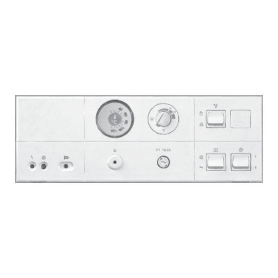
Front panel
Front view of the control, identifying indicators, switches, and gauges.
Summer mode switch
Function of the front-mounted summer mode switch for seasonal operation.
Override switch
Function of the front-mounted override switch for manual control.
Power switch
Function of the front-mounted power switch to turn the control on or off.
Routing Cables
Steps for properly routing cables into the control unit.
Power Supply
Instructions for connecting the main power supply cord to the unit.
Burner Connection
Details on connecting the burner to the control unit using quick-connect plugs.
Terminal Codes
Explanation of terminal codes used for burner control circuits.
Room Thermostat Connection
How to connect a room thermostat to the control unit.
Boiler/Space Heater Pump Connection
Information on connecting the boiler or space heater pump.
Boiler Sensor Connection
Instructions for connecting the boiler sensor.
Installation of the boiler sensor
Steps for inserting the boiler sensor into the sensor well.
DHW Pump Connection
Details on connecting the DHW (Domestic Hot Water) pump.
DHW Sensor Connection
Instructions for connecting the DHW sensor.
Alarm Output
Description of the dry contact alarm output and fault conditions.
Outdoor Temperature Sensor Installation
Steps and considerations for installing the outdoor temperature sensor.
Altering Settings
Fixed High Limit
Information on the fixed high limit safety cut-out and its adjustment.
Changing the Setting of the Fixed High Limit Safety Cut-out
Procedure to change the fixed high limit safety cut-out setting.
Adjustment to 100° C for side scales
How to adjust the fixed high limit to 100° C for specific scales.
Adjustable High Limit
Details on the adjustable high limit (AHL) and its settings.
Altering the Indoor/Outdoor Control Settings Internal
How to adjust internal settings related to indoor/outdoor control.
Factory settings
Default factory settings for heating curve slope and WWSD.
Slope adjustment
Explanation and calculation method for slope adjustment in heating curves.
Warm weather shut-down adjustment
How to adjust the warm weather shut-down (WWSD) setting for system control.
Start-up
After Installation
Checklist and steps to complete after installation is finished.
Checklist
Verification points to ensure proper installation before start-up.
Service binder
Instructions for filing technical documentation and storing the service binder.
Start-up Instructions
Steps for initial start-up of the control system.
Switches
Overview of front panel and internal switches (dial and DIP) for configuration.
Front panel switches
Description of front panel switches like Power, Summer Mode, and Override.
Dial switches
Explanation of dial switch functions and positions (S1 to S5).
DIP switches
Explanation of DIP switch functions and positions (S6, S7).
Troubleshooting
Diagnostics
Procedures for diagnosing system failures and issues.
Failure, cause, correction
Table listing common symptoms, their causes, and corrective actions.
Test points
Identification of test points for electrical diagnostics.
120V power flow
Description of the 120V power flow through the control.
Dial switch
Function of the dial switch (S2) for relay testing.
Front panel LEDs
Meaning of the front panel LEDs indicating system status or faults.
Temperature sensors
Information on sensor failures and their descriptions.
Outdoor temperature sensor resistance chart
Chart showing resistance values for outdoor temperature sensor at different temperatures.
Additional Information
Replacement Components
Instructions for replacing common components like fuses and limits.
Parts List
List of available replacement parts with part numbers and descriptions.
Wiring Diagram
Schematic showing electrical connections of the control system.
Technical Data
Specifications and technical data for the Vitotronic 100.
Protocol
Section to record altered settings and factory defaults.
Need help?
Do you have a question about the KW10B and is the answer not in the manual?
Questions and answers