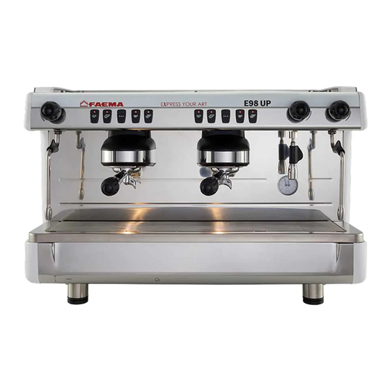
Summarization of Contents
Cup Warmer Operation
Activating the Cup Warmer
Instructions for activating the cup warmer by pressing a button and checking the light.
Heating Element Activation
Switch Sequence Warning
Emphasizes paying attention to the sequence of operating switches (1) and (1A).
Main Switch (1) and Resistance Switch (1a) Operation
Steps for operating the main switch (1) and resistance switch (1a) for heating.
Coffee Dispensing Operations
DT/A Version Coffee Dispensing
How to dispense coffee using keys, auto-stop, and continuous dispensing.
C/S Version Coffee Dispensing
How to dispense coffee using button (2) and stopping the process.
Coffee Dose Programming (DT/A Versions)
Accessing Programming Mode
Instructions to enter programming by pressing and holding the STOP/prog button (18).
Programming Coffee Doses
Steps to program coffee doses for specific buttons by dispensing coffee.
Troubleshooting Common Issues
Machine Operation Problems and Solutions
Lists issues like machine not working, not heating up, leaking, short dispensing time, etc., with causes and solutions.
Unified Control Board Configuration
DIP Switch Settings Overview
Table detailing DIP switch functions for machine configurations.
Connector Configuration (CN10, CN11, CN14)
Solenoid Valve Voltage Configuration
Explains the function of the bridge (A) on CN10/CN11 for 220V or 24V solenoid valves.
Detailed DIP Switch Functions
DIP Switch Settings Explained
Details the function of each DIP switch (Dip1-Dip8) and other settings.
Disassembly and Setting Procedures
Safety Precautions for Disassembly
General safety warnings regarding machine power, safety equipment, and cold operation.
Drip Tray Removal
Instructions and illustration for removing the drip tray.
Draining the Boiler Water
Instructions and illustration for draining water from the boiler.
Removing the Boiler Heating Element
Steps to remove the heating element after emptying the boiler.
Accessing the Electrical Box
Illustrated steps for accessing the electrical box, including removing the tray.
Safety Thermostat and Front Panel Maintenance
Safety Thermostat Location and Front Panel Removal
Illustration showing thermostat location and steps to remove the front panel.
Volumetric Pump and Pressurestat
Volumetric Pump Components Overview
Illustrations showing the components of the volumetric pump.
Pressurestat Adjustment and Components
Illustrations showing the pressurestat and its adjustment.
Electrical Wiring Diagrams
Control Board Wiring Diagram
Diagram showing connections for the control board components.
Power Supply Wiring Diagram (Star Configuration)
Wiring diagram illustrating the star configuration for the boiler resistance.
Power Supply Wiring Diagram (Triangle Configuration)
Wiring diagram illustrating the triangle configuration for the boiler resistance.
Power Supply Wiring Diagram (Single-Phase 16A)
Wiring diagram for single-phase 16A power supply configuration.
Power Supply Wiring Diagram (Single-Phase 13A)
Wiring diagram for single-phase 13A power supply configuration.
Power Supply Wiring Diagram (Single-Phase Full)
Wiring diagram for single-phase full power supply configuration.
Hydraulic Circuit Diagrams
DT/A Hydraulic Circuit Diagram
Diagram showing hydraulic components and flow for DT/A version.
DT/A Misc. Hydraulic Circuit Diagram
Diagram showing hydraulic components and flow for DT/A misc. version.
C/S Hydraulic Circuit Diagram
Diagram showing hydraulic components and flow for C/S version.


Need help?
Do you have a question about the M23UP and is the answer not in the manual?
Questions and answers